
Rating:
Information injection-pump assembly
ZEXEL
104746-1321
1047461321
ISUZU
8971078630
8971078630
Cross reference number
ZEXEL
104746-1321
1047461321
ISUZU
8971078630
8971078630
Zexel num
Bosch num
Firm num
Name
Calibration Data:
Adjustment conditions
Test oil
1404 Test oil ISO4113orSAEJ967d
1404 Test oil ISO4113orSAEJ967d
Test oil temperature
degC
45
45
50
Nozzle
105780-0060
Bosch type code
NP-DN0SD1510
Nozzle holder
105780-2150
Opening pressure
MPa
13
13
13.3
Opening pressure
kgf/cm2
133
133
136
Injection pipe
157805-7320
Injection pipe
Inside diameter - outside diameter - length (mm) mm 2-6-450
Inside diameter - outside diameter - length (mm) mm 2-6-450
Joint assembly
157641-4720
Tube assembly
157641-4020
Transfer pump pressure
kPa
20
20
20
Transfer pump pressure
kgf/cm2
0.2
0.2
0.2
Direction of rotation (viewed from drive side)
Right R
Right R
Injection timing adjustment
Pump speed
r/min
1000
1000
1000
Average injection quantity
mm3/st.
60.9
60.4
61.4
Difference in delivery
mm3/st.
3.5
Basic
*
Oil temperature
degC
50
48
52
Injection timing adjustment_02
Pump speed
r/min
500
500
500
Average injection quantity
mm3/st.
60
60
60
Oil temperature
degC
48
46
50
Injection timing adjustment_03
Pump speed
r/min
1000
1000
1000
Average injection quantity
mm3/st.
60.9
59.9
61.9
Difference in delivery
mm3/st.
3.5
Basic
*
Oil temperature
degC
50
48
52
Injection timing adjustment_04
Pump speed
r/min
1440
1440
1440
Average injection quantity
mm3/st.
58.9
58.9
58.9
Oil temperature
degC
50
48
52
Injection timing adjustment_05
Pump speed
r/min
1800
1800
1800
Average injection quantity
mm3/st.
59.2
59.2
59.2
Oil temperature
degC
50
48
52
Injection quantity adjustment
Pump speed
r/min
2100
2100
2100
Average injection quantity
mm3/st.
19.6
16.6
22.6
Difference in delivery
mm3/st.
5.5
Basic
*
Oil temperature
degC
52
50
54
Injection quantity adjustment_02
Pump speed
r/min
2300
2300
2300
Average injection quantity
mm3/st.
5
Oil temperature
degC
52
50
54
Injection quantity adjustment_03
Pump speed
r/min
2100
2100
2100
Average injection quantity
mm3/st.
19.6
16.6
22.6
Difference in delivery
mm3/st.
5.5
Oil temperature
degC
52
50
54
Governor adjustment
Pump speed
r/min
360
360
360
Average injection quantity
mm3/st.
13.2
11.2
15.2
Difference in delivery
mm3/st.
2
Basic
*
Oil temperature
degC
48
46
50
Governor adjustment_02
Pump speed
r/min
360
360
360
Average injection quantity
mm3/st.
13.2
11.2
15.2
Difference in delivery
mm3/st.
2
Oil temperature
degC
48
46
50
Timer adjustment
Pump speed
r/min
100
100
100
Average injection quantity
mm3/st.
74
69
79
Oil temperature
degC
48
46
50
Remarks
Full
Full
Timer adjustment_02
Pump speed
r/min
100
100
100
Average injection quantity
mm3/st.
74
69
79
Oil temperature
degC
48
46
50
Speed control lever angle
Pump speed
r/min
360
360
360
Average injection quantity
mm3/st.
0
0
0
Remarks
Magnet OFF at idling position
Magnet OFF at idling position
0000000901
Pump speed
r/min
1000
1000
1000
Overflow quantity
cm3/min
680
550
810
Oil temperature
degC
50
48
52
Stop lever angle
Pump speed
r/min
1000
1000
1000
Pressure
kPa
422
393
451
Pressure
kgf/cm2
4.3
4
4.6
Basic
*
Oil temperature
degC
50
48
52
Stop lever angle_02
Pump speed
r/min
1000
1000
1000
Pressure
kPa
422
393
451
Pressure
kgf/cm2
4.3
4
4.6
Basic
*
Oil temperature
degC
50
48
52
0000001101
Pump speed
r/min
1000
1000
1000
Timer stroke
mm
2.5
2.3
2.7
Basic
*
Oil temperature
degC
50
48
52
_02
Pump speed
r/min
1700
1700
1700
Timer stroke
mm
5.8
5.5
6.1
Basic
*
Oil temperature
degC
50
48
52
_03
Pump speed
r/min
520
520
520
Timer stroke
mm
0.5
0.1
1.3
_04
Pump speed
r/min
1000
1000
1000
Timer stroke
mm
2.5
2.3
2.7
Basic
*
_05
Pump speed
r/min
1440
1440
1440
Timer stroke
mm
3.9
3.6
4.2
_06
Pump speed
r/min
1700
1700
1700
Timer stroke
mm
5.8
5.4
6.2
Basic
*
_07
Pump speed
r/min
1950
1950
1950
Timer stroke
mm
7.8
7.5
8.2
0000001201
Max. applied voltage
V
8
8
8
Test voltage
V
13
12
14
0000001401
Pump speed
r/min
1000
1000
1000
Average injection quantity
mm3/st.
31.8
31.3
32.3
Timer stroke TA
mm
2.2
2.2
2.2
Timer stroke variation dT
mm
0.3
0.1
0.5
Basic
*
Oil temperature
degC
50
48
52
_02
Pump speed
r/min
1000
1000
1000
Average injection quantity
mm3/st.
31.8
30.8
32.8
Timer stroke variation dT
mm
0.3
-0.1
0.7
Basic
*
Oil temperature
degC
50
48
52
_03
Pump speed
r/min
1000
1000
1000
Average injection quantity
mm3/st.
16.7
15.7
17.7
Timer stroke variation dT
mm
1
0.4
1.6
Oil temperature
degC
50
48
52
Timing setting
K dimension
mm
3.3
3.2
3.4
KF dimension
mm
5.8
5.7
5.9
MS dimension
mm
0.7
0.6
0.8
Pre-stroke
mm
0.1
0.08
0.12
Control lever angle alpha
deg.
18
14
22
Control lever angle beta
deg.
31
26
36
Test data Ex:
0000001801 W-CSD ADJUSTMENT
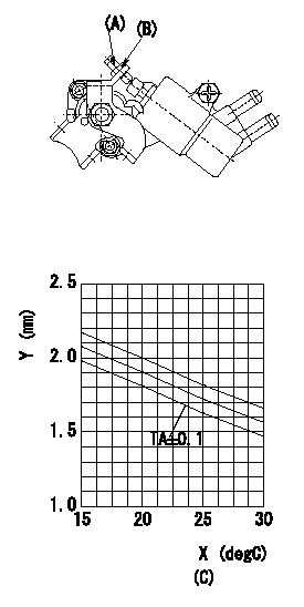
Adjustment of the W-CSD
1. Adjustment of the advance angle of the timer
(1)Determine the timer advance angle using the graph.
(2)(1) Adjust with the screw (A) so that the timer advance angle determined in the item (1) is obtained.
Y:Timer stroke TA
X:Temperature t
(C): timer stroke TA(mm)
----------
----------
----------
----------
0000001901 V-FICD ADJUSTMENT
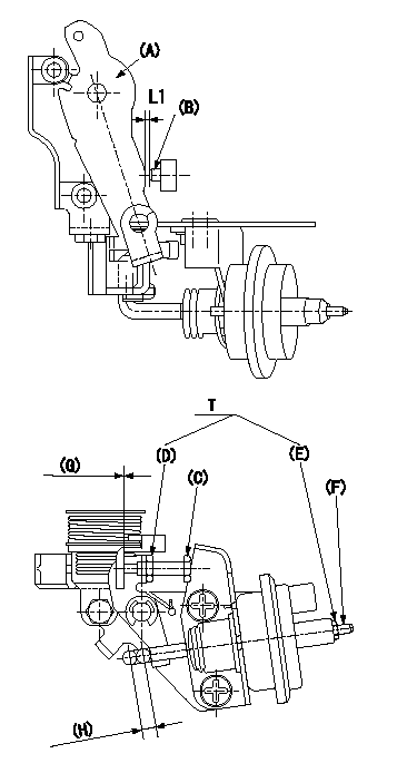
Adjustment of the V-FICD
1. Insert a shim L1 between the control lever (A) and the idle adjusting screw (B) and adjust using the FICD adjusting screw (C) so that the actuator moves through its full stroke. Then, fix using nut (D).
If adjustment with the FICD adjusting screw (C) is not possible, adjust by moving the actuator stroke with (E) and (F).
2. Apply P1{P2} pressure to the actuator and confirm that the actuator moves through its full stroke. After release, confirm that the gap between control lever (A) and FICD adjusting screw (C) is at least L2.
(G): exceeds L2 when releasing actuator
(H): actuator stroke L3
----------
L1=1.40+-0.1mm L2=0.5mm P1=-53.3kPa P2=-400mmHg
----------
T=3.4~4.9Nm(0.35~0.50kgfm)
----------
L1=1.40+-0.1mm L2=0.5mm P1=-53.3kPa P2=-400mmHg
----------
T=3.4~4.9Nm(0.35~0.50kgfm)
0000002001 STARTING I/Q ADJUSTMENT
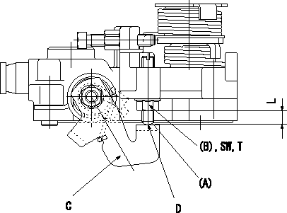
Starting injection quantity adjustment
Adjust the adjusting bolt A so that the starting injection quantity adjustment is within the standards.
Fix using nut (B).
Screw (A) protrusion: L
C = stop lever
D = no clearance
----------
L=2~8.5mm
----------
L=2~8.5mm T=6~9Nm(0.6~0.9kgfm) SW=SW10
----------
L=2~8.5mm
----------
L=2~8.5mm T=6~9Nm(0.6~0.9kgfm) SW=SW10