Rating:
Information injection-pump assembly
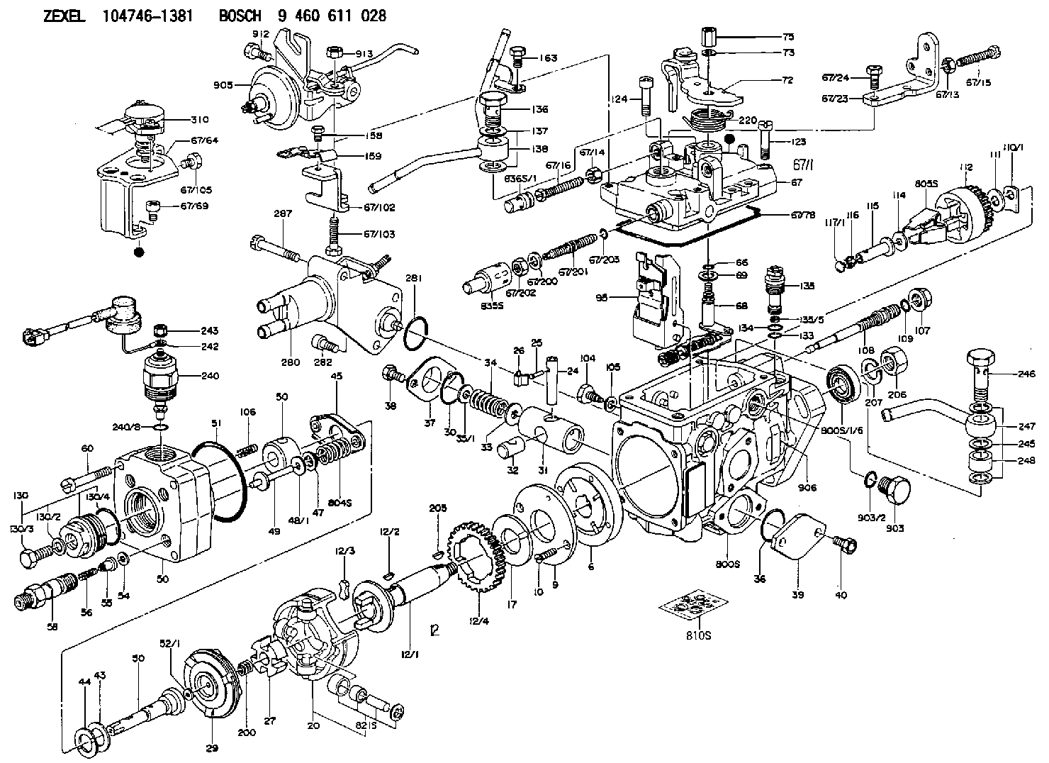
BOSCH
9 460 611 028
9460611028
ZEXEL
104746-1381
1047461381
ISUZU
8971091191
8971091191
Components :
| 0. | INJECTION-PUMP ASSEMBLY | 104746-1381 |
| 1. | _ | |
| 2. | FUEL INJECTION PUMP | 104646-1381 |
| 3. | NUMBER PLATE | 146924-5600 |
| 4. | _ | |
| 5. | CAPSULE | 146620-0120 |
| 6. | ADJUSTING DEVICE | 146679-3821 |
| 7. | NOZZLE AND HOLDER ASSY | 105118-5922 |
| 8. | Nozzle and Holder | 8-97109-103-1 |
| 9. | Open Pre:MPa(Kqf/cm2) | 18.1{185} |
| 10. | NOZZLE-HOLDER | 105048-3230 |
| 11. | NOZZLE | 105017-1730 |
Scheme ###:
| 1/6. | [1] | 146601-0700 | PACKING RING |
| 6. | [1] | 146100-0120 | SUPPLY PUMP |
| 9. | [1] | 146103-0000 | COVER |
| 10. | [2] | 139104-0000 | FLAT-HEAD SCREW |
| 12. | [1] | 146200-0820 | DRIVE SHAFT |
| 12/1. | [1] | 146200-0800 | DRIVE SHAFT |
| 12/2. | [1] | 146201-0000 | WOODRUFF KEY |
| 12/3. | [2] | 146202-0100 | DAMPER |
| 12/4. | [1] | 146203-0000 | TOOTHED GEAR |
| 17. | [1] | 146204-0000 | PLAIN WASHER |
| 20. | [1] | 146210-4120 | ROLLER SET |
| 24. | [1] | 146303-0000 | BEARING PIN |
| 25. | [1] | 146304-0000 | BEARING PIN |
| 26. | [1] | 146305-0000 | CLAMPING BAND |
| 27. | [1] | 146205-0100 | SLOTTED WASHER |
| 29. | [1] | 146220-0720 | CAM PLATE |
| 30. | [1] | 146600-0800 | O-RING |
| 31. | [1] | 146300-4000 | PUMP PLUNGER |
| 32. | [1] | 146301-0000 | SLIDING PIECE |
| 33. | [1] | 146603-0700 | SHIM |
| 34. | [1] | 146302-3500 | COMPRESSION SPRING |
| 34B. | [1] | 146302-3600 | COMPRESSION SPRING |
| 34C. | [1] | 146302-3400 | COMPRESSION SPRING |
| 35/1. | [0] | 146603-0700 | SHIM |
| 35/1. | [0] | 146603-0800 | SHIM |
| 35/1. | [0] | 146603-0900 | SHIM |
| 35/1. | [0] | 146603-1000 | SHIM |
| 35/1. | [0] | 146603-1100 | SHIM |
| 35/1. | [0] | 146603-3600 | SHIM |
| 36. | [1] | 146600-0800 | O-RING |
| 37. | [1] | 146310-0700 | COVER |
| 38. | [2] | 146620-5000 | BLEEDER SCREW |
| 39. | [1] | 146310-5100 | COVER |
| 40. | [2] | 146620-5000 | BLEEDER SCREW |
| 43. | [1] | 146230-0000 | SHIM |
| 44. | [1] | 146230-0100 | PLAIN WASHER |
| 45. | [1] | 146231-0001 | SLOTTED WASHER |
| 47. | [2] | 146233-0000 | SLOTTED WASHER |
| 48/1. | [2] | 146603-0000 | SHIM |
| 48/1. | [2] | 146603-0100 | SHIM |
| 48/1. | [2] | 146603-0200 | SHIM |
| 48/1. | [2] | 146603-0300 | SHIM |
| 48/1. | [2] | 146603-0400 | SHIM |
| 48/1. | [2] | 146603-0500 | SHIM |
| 48/1. | [2] | 146603-0600 | SHIM |
| 48/1. | [2] | 146690-1400 | SHIM |
| 48/1. | [2] | 146690-1500 | SHIM |
| 48/1. | [2] | 146690-1600 | SHIM |
| 48/1. | [2] | 146690-1700 | SHIM |
| 48/1. | [2] | 146690-1800 | SHIM |
| 48/1. | [2] | 146690-1900 | SHIM |
| 48/1. | [2] | 146690-5800 | SHIM |
| 48/1. | [2] | 146690-5900 | SHIM |
| 48/1. | [2] | 146690-6000 | SHIM |
| 48/1. | [2] | 146690-6100 | SHIM |
| 48/1. | [2] | 146690-6200 | SHIM |
| 48/1. | [2] | 146690-6300 | SHIM |
| 48/1. | [2] | 146690-6400 | SHIM |
| 48/1. | [2] | 146690-6500 | SHIM |
| 48/1. | [2] | 146690-6600 | SHIM |
| 48/1. | [2] | 146690-6700 | SHIM |
| 48/1. | [2] | 146690-6800 | SHIM |
| 48/1. | [2] | 146690-6900 | SHIM |
| 48/1. | [2] | 146690-7000 | SHIM |
| 48/1. | [2] | 146690-7100 | SHIM |
| 48/1. | [2] | 146690-7200 | SHIM |
| 48/1. | [2] | 146690-7300 | SHIM |
| 48/1. | [2] | 146690-7400 | SHIM |
| 48/1. | [2] | 146690-7500 | SHIM |
| 48/1. | [2] | 146690-7800 | SHIM |
| 49. | [2] | 146234-0600 | GUIDE PIN |
| 50. | [1] | 146402-3420 | HYDRAULIC HEAD |
| 50. | [1] | 146402-3420 | HYDRAULIC HEAD |
| 50. | [1] | 146402-3420 | HYDRAULIC HEAD |
| 51. | [1] | 146600-0000 | O-RING |
| 52/1. | [1] | 146420-0000 | SHIM |
| 52/1. | [1] | 146420-0100 | SHIM |
| 52/1. | [1] | 146420-0200 | SHIM |
| 52/1. | [1] | 146420-0300 | SHIM |
| 52/1. | [1] | 146420-0400 | SHIM |
| 52/1. | [1] | 146420-0500 | SHIM |
| 52/1. | [1] | 146420-0600 | SHIM |
| 52/1. | [1] | 146420-0700 | SHIM |
| 52/1. | [1] | 146420-0800 | SHIM |
| 52/1. | [1] | 146420-0900 | SHIM |
| 52/1. | [1] | 146420-1000 | SHIM |
| 52/1. | [1] | 146420-1100 | SHIM |
| 52/1. | [1] | 146420-1200 | SHIM |
| 52/1. | [1] | 146420-1300 | SHIM |
| 52/1. | [1] | 146420-1400 | SHIM |
| 52/1. | [1] | 146420-1500 | SHIM |
| 52/1. | [1] | 146420-1600 | SHIM |
| 52/1. | [1] | 146420-1700 | SHIM |
| 52/1. | [1] | 146420-1800 | SHIM |
| 52/1. | [1] | 146420-1900 | SHIM |
| 52/1. | [1] | 146420-2000 | SHIM |
| 52/1. | [1] | 146420-2100 | SHIM |
| 52/1. | [1] | 146420-2200 | SHIM |
| 52/1. | [1] | 146420-2300 | SHIM |
| 52/1. | [1] | 146420-2400 | SHIM |
| 52/1. | [1] | 146420-2500 | SHIM |
| 52/1. | [1] | 146420-2600 | SHIM |
| 52/1. | [1] | 146420-2700 | SHIM |
| 52/1. | [1] | 146420-2800 | SHIM |
| 52/1. | [1] | 146420-2900 | SHIM |
| 52/1. | [1] | 146420-3000 | SHIM |
| 52/1. | [1] | 146420-3100 | SHIM |
| 52/1. | [1] | 146420-3200 | SHIM |
| 52/1. | [1] | 146420-3300 | SHIM |
| 52/1. | [1] | 146420-3400 | SHIM |
| 52/1. | [1] | 146420-3500 | SHIM |
| 52/1. | [1] | 146420-3600 | SHIM |
| 52/1. | [1] | 146420-3700 | SHIM |
| 52/1. | [1] | 146420-3800 | SHIM |
| 52/1. | [1] | 146420-3900 | SHIM |
| 52/1. | [1] | 146420-4000 | SHIM |
| 52/1. | [1] | 146420-4100 | SHIM |
| 52/1. | [1] | 146420-4200 | SHIM |
| 52/1. | [1] | 146420-4300 | SHIM |
| 52/1. | [1] | 146420-4400 | SHIM |
| 52/1. | [1] | 146420-4500 | SHIM |
| 52/1. | [1] | 146420-4600 | SHIM |
| 52/1. | [1] | 146420-4700 | SHIM |
| 52/1. | [1] | 146420-4800 | SHIM |
| 52/1. | [1] | 146420-4900 | SHIM |
| 52/1. | [1] | 146420-5000 | SHIM |
| 52/1. | [1] | 146420-5100 | SHIM |
| 52/1. | [1] | 146420-5200 | SHIM |
| 52/1. | [1] | 146420-5300 | SHIM |
| 52/1. | [1] | 146420-5400 | SHIM |
| 52/1. | [1] | 146420-5500 | SHIM |
| 52/1. | [1] | 146420-5600 | SHIM |
| 52/1. | [1] | 146420-5700 | SHIM |
| 52/1. | [1] | 146420-5800 | SHIM |
| 54. | [4] | 146433-0100 | GASKET |
| 55. | [4] | 146430-1420 | DELIVERY-VALVE ASSEMBLY |
| 56. | [4] | 146432-0200 | COMPRESSION SPRING |
| 58. | [4] | 146440-1520 | FITTING |
| 60. | [4] | 139106-0100 | FLAT-HEAD SCREW |
| 66. | [1] | 146600-0100 | O-RING |
| 67. | [1] | 146503-8920 | GOVERNOR COVER |
| 67/1. | [1] | 146508-1221 | GOVERNOR COVER |
| 67/13. | [1] | 013020-6040 | UNION NUT |
| 67/14. | [1] | 146621-1700 | UNION NUT |
| 67/15. | [1] | 146526-2800 | BLEEDER SCREW |
| 67/16. | [1] | 146526-2800 | BLEEDER SCREW |
| 67/23. | [1] | 146932-0701 | BRACKET |
| 67/24. | [2] | 139006-4500 | BLEEDER SCREW |
| 67/64. | [1] | 146932-0800 | BRACKET |
| 67/69. | [2] | 010206-1040 | HEX-SOCKET-HEAD CAP SCREW |
| 67/78. | [1] | 146600-4400 | SEAL RING |
| 67/102. | [1] | 146932-1100 | BRACKET |
| 67/103. | [1] | 139006-4800 | BLEEDER SCREW |
| 67/105. | [1] | 139006-4400 | BLEEDER SCREW |
| 67/200. | [1] | 139308-0300 | PLAIN WASHER |
| 67/201. | [1] | 146545-3400 | THREADED PIN |
| 67/201B. | [1] | 146545-3500 | THREADED PIN |
| 67/201C. | [1] | 146545-3600 | THREADED PIN |
| 67/202. | [1] | 139208-0900 | UNION NUT |
| 67/203. | [1] | 146600-1200 | O-RING |
| 68. | [1] | 146810-1020 | CONTROL SHAFT |
| 69. | [1] | 139310-0200 | PLAIN WASHER |
| 72. | [1] | 146831-1800 | CONTROL LEVER |
| 72B. | [1] | 146831-1900 | CONTROL LEVER |
| 73. | [1] | 014110-6440 | LOCKING WASHER |
| 75. | [1] | 146621-4600 | UNION NUT |
| 95. | [1] | 146865-2020 | FULCRUM LEVER |
| 104. | [2] | 146568-0000 | SLOTTED SPRING PIN |
| 105. | [2] | 026508-1140 | GASKET |
| 106. | [2] | 146588-0500 | COILED SPRING |
| 107. | [1] | 146569-0300 | UNION NUT |
| 108. | [1] | 146570-0100 | GOVERNOR SHAFT |
| 109. | [1] | 146600-0400 | O-RING |
| 110/1. | [1] | 146571-0000 | SHIM |
| 110/1. | [1] | 146571-0100 | SHIM |
| 110/1. | [1] | 146571-0200 | SHIM |
| 110/1. | [1] | 146571-0300 | SHIM |
| 110/1. | [1] | 146571-0400 | SHIM |
| 110/1. | [1] | 146571-0500 | SHIM |
| 110/1. | [1] | 146571-0600 | SHIM |
| 110/1. | [1] | 146571-0700 | SHIM |
| 110/1. | [1] | 146571-0800 | SHIM |
| 111. | [1] | 146602-0600 | PLAIN WASHER |
| 112. | [1] | 146572-0020 | FLYWEIGHT ASSEMBLY |
| 114. | [1] | 146602-0500 | PLAIN WASHER |
| 115. | [1] | 146575-2000 | SLIDING SLEEVE |
| 116. | [1] | 146576-0200 | CAP |
| 117/1. | [1] | 146577-1800 | PLUG |
| 117/1. | [1] | 146577-1900 | PLUG |
| 117/1. | [1] | 146577-2000 | PLUG |
| 117/1. | [1] | 146577-2100 | PLUG |
| 117/1. | [1] | 146577-2200 | PLUG |
| 117/1. | [1] | 146577-2300 | PLUG |
| 117/1. | [1] | 146577-2400 | PLUG |
| 117/1. | [1] | 146577-2500 | PLUG |
| 117/1. | [1] | 146577-2600 | PLUG |
| 117/1. | [1] | 146577-2700 | PLUG |
| 117/1. | [1] | 146577-2800 | PLUG |
| 117/1. | [1] | 146577-2900 | PLUG |
| 117/1. | [1] | 146577-3000 | PLUG |
| 117/1. | [1] | 146577-3100 | PLUG |
| 117/1. | [1] | 146577-3200 | PLUG |
| 117/1. | [1] | 146577-3300 | PLUG |
| 117/1. | [1] | 146577-6700 | PLUG |
| 117/1. | [1] | 146577-6800 | PLUG |
| 117/1. | [1] | 146577-6900 | PLUG |
| 117/1. | [1] | 146577-7000 | PLUG |
| 117/1. | [1] | 146577-7100 | PLUG |
| 117/1. | [1] | 146577-7200 | PLUG |
| 117/1. | [1] | 146577-7300 | PLUG |
| 117/1. | [1] | 146577-7400 | PLUG |
| 117/1. | [1] | 146577-7500 | PLUG |
| 117/1. | [1] | 146577-7600 | PLUG |
| 117/1. | [1] | 146577-7700 | PLUG |
| 117/1. | [1] | 146577-7800 | PLUG |
| 117/1. | [1] | 146577-7900 | PLUG |
| 117/1. | [1] | 146577-8000 | PLUG |
| 117/1. | [1] | 146577-8100 | PLUG |
| 117/1. | [1] | 146877-0000 | PLUG |
| 117/1. | [1] | 146877-0100 | PLUG |
| 117/1. | [1] | 146877-0200 | PLUG |
| 117/1. | [1] | 146877-0300 | PLUG |
| 117/1. | [1] | 146877-4700 | PLUG |
| 117/1. | [1] | 146877-4800 | PLUG |
| 117/1. | [1] | 146877-4900 | PLUG |
| 117/1. | [1] | 146877-5000 | PLUG |
| 123. | [3] | 139106-0200 | FLAT-HEAD SCREW |
| 124. | [1] | 146620-0500 | HEX-SOCKET-HEAD CAP SCREW |
| 130. | [1] | 146421-0320 | CAPSULE |
| 130/2. | [1] | 026508-1140 | GASKET |
| 130/3. | [1] | 146422-0300 | BLEEDER SCREW |
| 130/4. | [1] | 146600-0500 | O-RING |
| 133. | [1] | 146600-0600 | O-RING |
| 134. | [1] | 146600-0700 | O-RING |
| 135. | [1] | 146110-0720 | CONTROL VALVE |
| 135/5. | [1] | 146114-0000 | SPRING WASHER |
| 136. | [1] | 146120-0020 | OVER FLOW VALVE |
| 137. | [2] | 139512-0500 | GASKET |
| 138. | [1] | 146666-8920 | INLET UNION |
| 158. | [1] | 020105-0940 | BLEEDER SCREW |
| 159. | [1] | 146932-0900 | PLATE |
| 163. | [1] | 020146-1270 | BLEEDER SCREW |
| 205. | [1] | 025804-1610 | WOODRUFF KEY |
| 220. | [1] | 146587-5000 | COILED SPRING |
| 240. | [1] | 146650-1220 | PULLING ELECTROMAGNET |
| 240/8. | [1] | 146600-1700 | O-RING |
| 242. | [1] | 146658-7320 | WIRE |
| 243. | [1] | 146621-1000 | UNION NUT |
| 245. | [2] | 139512-0500 | GASKET |
| 246. | [1] | 027412-2440 | EYE BOLT |
| 247. | [1] | 146609-4620 | INLET UNION |
| 280. | [1] | 146361-0523 | START ADVANCE ASSY |
| 281. | [1] | 146600-0800 | O-RING |
| 282. | [2] | 010206-1240 | HEX-SOCKET-HEAD CAP SCREW |
| 287. | [1] | 020306-4040 | O-RING |
| 310. | [1] | 146684-5720 | POTENTCIOMETER |
| 310/1. | [1] | 146684-5700 | POTENTCIOMETER |
| 310/2. | [2] | 139104-0400 | FLAT-HEAD SCREW |
| 310/3. | [1] | 146621-0500 | UNION NUT |
| 310/4. | [1] | 146620-2900 | FLAT-HEAD SCREW |
| 310/5. | [1] | 146614-2300 | JOINT CONNECTION |
| 310/6. | [1] | 146661-0401 | BOOT |
| 800S. | [1] | 146018-6320 | PUMP HOUSING |
| 800S/1/6. | [1] | 146601-0700 | PACKING RING |
| 804S. | [1] | 146232-0720 | COMPRESSION SPRING |
| 805S. | [1] | 146574-0120 | PARTS SET |
| 810S. | [1] | 146600-1120 | REPAIR SET |
| 821S. | [1] | 146210-5720 | ROLLER SET |
| 835S. | [1] | 146598-1000 | CAP |
| 836S/1. | [1] | 146598-0600 | CAP |
| 836S/1. | [1] | 146598-0700 | CAP |
| 836S/1. | [1] | 146598-0800 | CAP |
| 836S/1. | [1] | 146598-0900 | CAP |
| 903. | [1] | 146620-0120 | CAPSULE |
| 903/2. | [1] | 146600-1300 | O-RING |
| 905. | [1] | 146679-3821 | ADJUSTING DEVICE |
| 906. | [1] | 146924-5600 | NAMEPLATE |
| 912. | [1] | 139006-4700 | BLEEDER SCREW |
| 913. | [1] | 013020-6040 | UNION NUT |
Include in #2:
104746-1381
as INJECTION-PUMP ASSEMBLY
Cross reference number
BOSCH
9 460 611 028
9460611028
ZEXEL
104746-1381
1047461381
ISUZU
8971091191
8971091191
Zexel num
Bosch num
Firm num
Name
104746-1381
9 460 611 028
8971091191 ISUZU
INJECTION-PUMP ASSEMBLY
4JA1 K
4JA1 K
Calibration Data:
Adjustment conditions
Test oil
1404 Test oil ISO4113orSAEJ967d
1404 Test oil ISO4113orSAEJ967d
Test oil temperature
degC
45
45
50
Nozzle
105780-0060
Bosch type code
NP-DN0SD1510
Nozzle holder
105780-2150
Opening pressure
MPa
13
13
13.3
Opening pressure
kgf/cm2
133
133
136
Injection pipe
157805-7320
Injection pipe
Inside diameter - outside diameter - length (mm) mm 2-6-450
Inside diameter - outside diameter - length (mm) mm 2-6-450
Joint assembly
157641-4720
Tube assembly
157641-4020
Transfer pump pressure
kPa
20
20
20
Transfer pump pressure
kgf/cm2
0.2
0.2
0.2
Direction of rotation (viewed from drive side)
Right R
Right R
Timer measuring device installation position
Low pressure side LOW PRESSURE SIDE
Low pressure side LOW PRESSURE SIDE
Injection timing adjustment
Pump speed
r/min
1150
1150
1150
Average injection quantity
mm3/st.
56.7
56.2
57.2
Difference in delivery
mm3/st.
4.5
Basic
*
Oil temperature
degC
50
48
52
Injection timing adjustment_02
Pump speed
r/min
2350
2350
2350
Average injection quantity
mm3/st.
24.3
20.8
27.8
Oil temperature
degC
55
52
58
Injection timing adjustment_03
Pump speed
r/min
1900
1900
1900
Average injection quantity
mm3/st.
67.8
62.8
72.8
Oil temperature
degC
52
50
54
Injection timing adjustment_04
Pump speed
r/min
1150
1150
1150
Average injection quantity
mm3/st.
56.7
55.7
57.7
Oil temperature
degC
50
48
52
Injection timing adjustment_05
Pump speed
r/min
750
750
750
Average injection quantity
mm3/st.
39.1
34.6
43.6
Oil temperature
degC
50
48
52
Injection timing adjustment_06
Pump speed
r/min
500
500
500
Average injection quantity
mm3/st.
31
26.5
35.5
Oil temperature
degC
48
46
50
Injection quantity adjustment
Pump speed
r/min
2350
2350
2350
Average injection quantity
mm3/st.
24.3
21.3
27.3
Difference in delivery
mm3/st.
4
Basic
*
Oil temperature
degC
55
52
58
Injection quantity adjustment_02
Pump speed
r/min
2700
2700
2700
Average injection quantity
mm3/st.
5
Oil temperature
degC
55
52
58
Governor adjustment
Pump speed
r/min
385
385
385
Average injection quantity
mm3/st.
7.3
5.3
9.3
Difference in delivery
mm3/st.
2
Basic
*
Oil temperature
degC
48
46
50
Governor adjustment_02
Pump speed
r/min
550
550
550
Average injection quantity
mm3/st.
3
Oil temperature
degC
48
46
50
Governor adjustment_03
Pump speed
r/min
385
385
385
Average injection quantity
mm3/st.
7.3
4.8
9.8
Oil temperature
degC
48
46
50
Timer adjustment
Pump speed
r/min
100
100
100
Average injection quantity
mm3/st.
60
10
110
Basic
*
Oil temperature
degC
48
46
50
Remarks
Full
Full
Speed control lever angle
Pump speed
r/min
385
385
385
Average injection quantity
mm3/st.
0
0
0
Oil temperature
degC
48
46
50
Remarks
Magnet OFF
Magnet OFF
0000000901
Pump speed
r/min
1400
1400
1400
Overflow quantity
cm3/min
360
210
510
Oil temperature
degC
50
48
52
Stop lever angle
Pump speed
r/min
1400
1400
1400
Pressure
kPa
412
392
432
Pressure
kgf/cm2
4.2
4
4.4
Basic
*
Oil temperature
degC
50
48
52
Stop lever angle_02
Pump speed
r/min
1400
1400
1400
Pressure
kPa
412
392
432
Pressure
kgf/cm2
4.2
4
4.4
Oil temperature
degC
50
48
52
Stop lever angle_03
Pump speed
r/min
1900
1900
1900
Pressure
kPa
559
530
588
Pressure
kgf/cm2
5.7
5.4
6
Oil temperature
degC
50
48
52
0000001101
Pump speed
r/min
1400
1400
1400
Timer stroke
mm
2.7
2.5
2.9
Basic
*
Oil temperature
degC
50
48
52
_02
Pump speed
r/min
1150
1150
1150
Timer stroke
mm
1
0.3
1.7
Oil temperature
degC
50
48
52
_03
Pump speed
r/min
1400
1400
1400
Timer stroke
mm
2.7
2.4
3
Oil temperature
degC
50
48
52
_04
Pump speed
r/min
1600
1600
1600
Timer stroke
mm
3.9
3.3
4.5
Oil temperature
degC
50
48
52
_05
Pump speed
r/min
1950
1950
1950
Timer stroke
mm
5.3
4.9
5.7
Oil temperature
degC
50
48
52
0000001201
Max. applied voltage
V
8
8
8
Test voltage
V
13
12
14
Timing setting
K dimension
mm
3.1
3
3.2
KF dimension
mm
5.5
5.4
5.6
MS dimension
mm
0.8
0.7
0.9
Pre-stroke
mm
0.45
0.43
0.47
Control lever angle alpha
deg.
18
14
22
Control lever angle beta
deg.
35
30
40
Test data Ex:
0000001801 POTENTIOMETER ADJUSTMENT
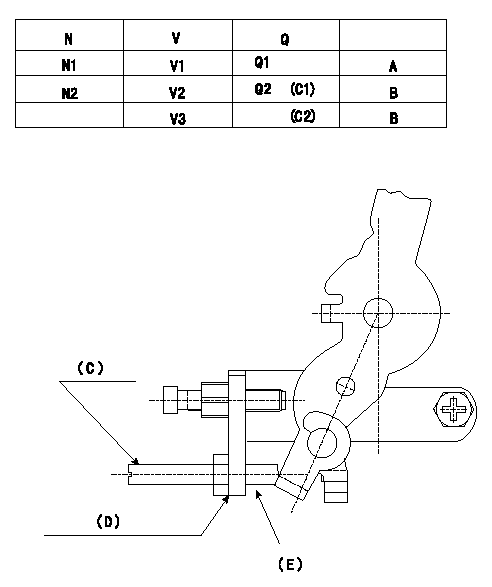
Potentiometer adjusting specifications (oval)
N:Pump speed
V:Output voltage
Q:Injection quantity
A:Adjusting point
B:Checking point
C1:Idle
C2:Full lever position
Adjusting method (applied voltage Vi, dummy bolt method)
1. Hold the dummy bolt (C) against the control lever at position N = N1 (r/min) and Q = Q1 (mm3/st) and fix using the lock nut.
2. When adjusting the potentiometer, position the control lever against the dummy bolt (A) and adjust so that the output voltage is V1 (V).
3. After completing adjustment, remove the dummy bolt (C) and confirm that the potentiometer output voltage is within the adjustment specifications when the control lever is in the idle position.
(D): Bracket for mounting the dummy bolt
(E): Dummy bolt and nut part number 146526-3300 (bolt) 42 mm
Corresponding to 013020-6040 (nut)
----------
N1=750r/min V1=3.80+-0.03V Q1=9.7+-1.0mm3/st Vi=10V
----------
N1=750r/min N2=385r/min V1=3.80+-0.03V V2=1.62+-0.45V V3=(7.24+-0.45)V Q1=9.7+-1mm3/st Q2=7.3+-2.0mm3/st
----------
N1=750r/min V1=3.80+-0.03V Q1=9.7+-1.0mm3/st Vi=10V
----------
N1=750r/min N2=385r/min V1=3.80+-0.03V V2=1.62+-0.45V V3=(7.24+-0.45)V Q1=9.7+-1mm3/st Q2=7.3+-2.0mm3/st
0000001901 W-CSD ADJUSTMENT
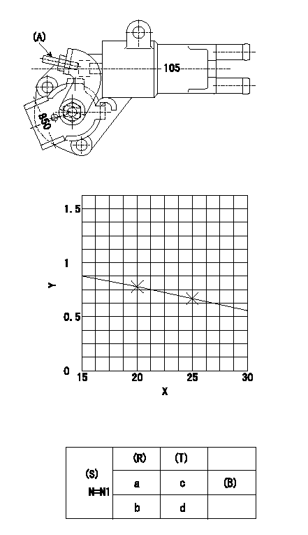
Adjustment of the W-CSD
Adjustment of the timer advance angle
1. Determine the timer advance angle using the graph (graph TA).
2. Adjust with the screw (A) so that the timer advance angle determined in item 1 is obtained.
X:Temperature t (deg C)
Y:Timer stroke TA (mm)
(S) Cooling water temperature: increase direction
(R) Cooling water temperature (deg C)
(T) Timer piston stroke (mm)
(B) Standard point
N:Pump speed
----------
TA=-0.0216t+1.21(-20<=t<=60)
----------
N1=500r/min a=20degC b=-20degC c=0.8+-0.4mm d=1.6+-0.6mm
----------
TA=-0.0216t+1.21(-20<=t<=60)
----------
N1=500r/min a=20degC b=-20degC c=0.8+-0.4mm d=1.6+-0.6mm
0000002001 V-FICD ADJUSTMENT
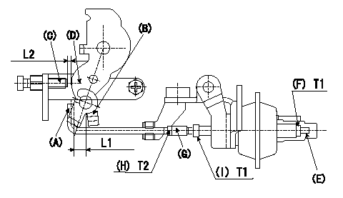
Adjustment of the V-FICD
1. Mount the V-FICD after the completion of potentiometer adjustment.
2. Confirm that the clearance between the control lever (B) and the actuator rod (A) is at least L1.
3. Insert the L2 shim between the control lever (D) and the idle set screw (C).
4. Adjust the stroke adjusting screw (E) so that the actuator moves through its full stroke, then fix using nut (F).
Note
When adjustment is not possible using the stroke adjusting screw (E), move the actuator rod position using (G), (H) and (I).
Adjust again the stroke with (E) and (F).
5. Apply negative pressure P1 to the actuator and confirm the full stroke.
6. After releasing negative pressure, re-confirm that the clearance between (A) and (B) is at least L1.
----------
L1=1mm L2=1.30+-0.1mm P1=-53.3kPa(-400mmHg)
----------
L1=1mm L2=1.30+-0.1mm
----------
L1=1mm L2=1.30+-0.1mm P1=-53.3kPa(-400mmHg)
----------
L1=1mm L2=1.30+-0.1mm
Have questions with 104746-1381?
Group cross 104746-1381 ZEXEL
Isuzu
Isuzu
Isuzu
Isuzu
Isuzu
Nissan
Isuzu
Isuzu
Isuzu
Isuzu
Isuzu
104746-1381
9 460 611 028
8971091191
INJECTION-PUMP ASSEMBLY
4JA1
4JA1