Rating:
Information injection-pump assembly
ZEXEL
106682-3040
1066823040
Service parts 106682-3040 INJECTION-PUMP ASSEMBLY:
1.
_
5.
AUTOM. ADVANCE MECHANIS
8.
_
9.
_
11.
Nozzle and Holder
23600-3140A
12.
Open Pre:MPa(Kqf/cm2)
17.7{180}/21.6{220}
14.
NOZZLE
Include in #1:
106682-3040
as INJECTION-PUMP ASSEMBLY
Cross reference number
ZEXEL
106682-3040
1066823040
Zexel num
Bosch num
Firm num
Name
106682-3040
INJECTION-PUMP ASSEMBLY
14CA PE6P,6PD PE
14CA PE6P,6PD PE
Calibration Data:
Adjustment conditions
Test oil
1404 Test oil ISO4113 or {SAEJ967d}
1404 Test oil ISO4113 or {SAEJ967d}
Test oil temperature
degC
40
40
45
Nozzle and nozzle holder
105780-8130
Bosch type code
EFEP215A
Nozzle
105780-0050
Bosch type code
DN6TD119NP1T
Nozzle holder
105780-2090
Bosch type code
EFEP215
Opening pressure
MPa
17.2
Opening pressure
kgf/cm2
175
Injection pipe
Outer diameter - inner diameter - length (mm) mm 8-4-1000
Outer diameter - inner diameter - length (mm) mm 8-4-1000
Overflow valve
134424-0820
Overflow valve opening pressure
kPa
127
107
147
Overflow valve opening pressure
kgf/cm2
1.3
1.1
1.5
Tester oil delivery pressure
kPa
157
157
157
Tester oil delivery pressure
kgf/cm2
1.6
1.6
1.6
Direction of rotation (viewed from drive side)
Right R
Right R
Injection timing adjustment
Direction of rotation (viewed from drive side)
Right R
Right R
Injection order
1-4-2-6-
3-5
Pre-stroke
mm
3.3
3.27
3.33
Beginning of injection position
Drive side NO.1
Drive side NO.1
Difference between angles 1
Cal 1-4 deg. 60 59.75 60.25
Cal 1-4 deg. 60 59.75 60.25
Difference between angles 2
Cyl.1-2 deg. 120 119.75 120.25
Cyl.1-2 deg. 120 119.75 120.25
Difference between angles 3
Cal 1-6 deg. 180 179.75 180.25
Cal 1-6 deg. 180 179.75 180.25
Difference between angles 4
Cal 1-3 deg. 240 239.75 240.25
Cal 1-3 deg. 240 239.75 240.25
Difference between angles 5
Cal 1-5 deg. 300 299.75 300.25
Cal 1-5 deg. 300 299.75 300.25
Injection quantity adjustment
Adjusting point
A
Rack position
14.7
Pump speed
r/min
1150
1150
1150
Average injection quantity
mm3/st.
437
433
441
Max. variation between cylinders
%
0
-3
3
Basic
*
Fixing the lever
*
Boost pressure
kPa
109
109
Boost pressure
mmHg
820
820
Injection quantity adjustment_02
Adjusting point
B
Rack position
R2(10.8)
Pump speed
r/min
700
700
700
Average injection quantity
mm3/st.
195
192
198
Fixing the lever
*
Boost pressure
kPa
0
0
0
Boost pressure
mmHg
0
0
0
Injection quantity adjustment_03
Adjusting point
D
Rack position
6.2+-0.5
Pump speed
r/min
250
250
250
Average injection quantity
mm3/st.
11.5
8.5
14.5
Max. variation between cylinders
%
0
-15
15
Fixing the rack
*
Boost pressure
kPa
0
0
0
Boost pressure
mmHg
0
0
0
Boost compensator adjustment
Pump speed
r/min
700
700
700
Rack position
R2(10.8)
Boost pressure
kPa
25.3
22.6
28
Boost pressure
mmHg
190
170
210
Boost compensator adjustment_02
Pump speed
r/min
700
700
700
Rack position
R1(14.7)
Boost pressure
kPa
96
96
96
Boost pressure
mmHg
720
720
720
Test data Ex:
Governor adjustment
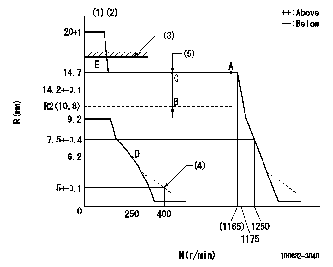
N:Pump speed
R:Rack position (mm)
(1)Target notch: K
(2)Tolerance for racks not indicated: +-0.05mm.
(3)Boost compensator excessive fuel lever at operation: L1 (at 0 boost pressure)
(4)Damper spring setting
(5)Boost compensator stroke: BCL
----------
K=7 L1=16.7+-0.1mm BCL=(3.9)mm
----------
----------
K=7 L1=16.7+-0.1mm BCL=(3.9)mm
----------
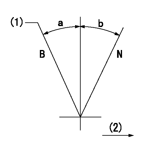
Speed control lever angle
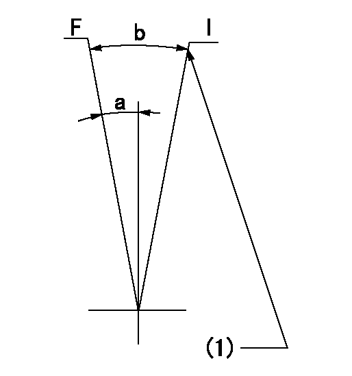
F:Full speed
I:Idle
(1)Stopper bolt setting
----------
----------
a=(10deg)+-5deg b=(33deg)+-5deg
----------
----------
a=(10deg)+-5deg b=(33deg)+-5deg
Stop lever angle
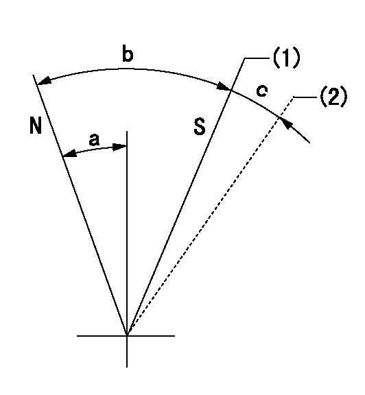
N:Pump normal
S:Stop the pump.
(1)Contacts inner stopper.
(2)Contacts outer stopper.
----------
----------
a=27deg+-5deg b=53deg+-5deg c=(11deg)
----------
----------
a=27deg+-5deg b=53deg+-5deg c=(11deg)
0000001101
N:Normal
B:When boosted
(1)Rack position = aa at boost pressure 0.
(2)Drive side
----------
aa=16.7+-0.1mm
----------
a=(18deg) b=(15deg)
----------
aa=16.7+-0.1mm
----------
a=(18deg) b=(15deg)
0000001501 Q ADJUSTMENT PIPING
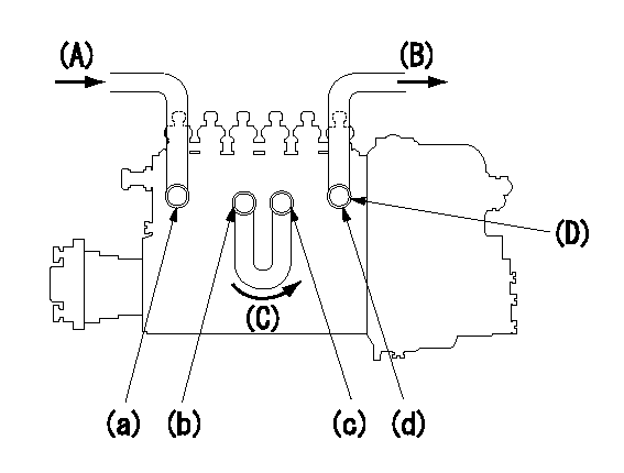
Fuel hose adjusting procedure
Fuel inlet hose A
Fuel inlet hose B
Fuel hose C ( (for bypass)
(D) Overflow valve
1. Because the pump gallery is divided into two, be careful of the fuel piping.
(1)Connect the fuel inlet hose to port (a).
(2)Connect the fuel hose (for bypass) to ports (b) and (c).
(3)Assemble the overflow valve (D) to the fuel outlet hose and connect to port (d).
----------
----------
----------
----------
Timing setting
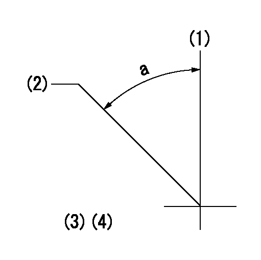
(1)Pump vertical direction
(2)Coupling's key groove position at No 1 cylinder's beginning of injection
(3)B.T.D.C.: aa
(4)-
----------
aa=20deg
----------
a=(50deg)
----------
aa=20deg
----------
a=(50deg)
Have questions with 106682-3040?
Group cross 106682-3040 ZEXEL
Hino
Hino
Hino
Hino
Hino
106682-3040
INJECTION-PUMP ASSEMBLY