Rating:
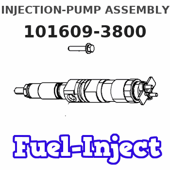
Information injection-pump assembly
BOSCH
9 400 615 917
9400615917
ZEXEL
101609-3800
1016093800
KOMATSU
4063910
4063910
Compare Prices: .
As an associate, we earn commssions on qualifying purchases through the links below

$436.80
24 Oct 2022
US: Inrox
4-40 x 1-1/4 Flat Head Machine Screws Stainless Steel 18-8 Qty 5000
Fastenere Phillips Flat Head Machine Screw || Phillips
Fastenere Phillips Flat Head Machine Screw || Phillips

$3,539.94
20 Aug 2020
-: -
Genuine Cummins 4063910 PUMP,FUEL INJECTION
Factory Direct Shipped Genuine Cummins Part || Availability can vary, please contact for availability before ordering || May take up to 20 business days to ship. Shipping depends upon availability
Factory Direct Shipped Genuine Cummins Part || Availability can vary, please contact for availability before ordering || May take up to 20 business days to ship. Shipping depends upon availability
Service parts 101609-3800 INJECTION-PUMP ASSEMBLY:
1.
_


5.
AUTOM. ADVANCE MECHANIS
6.
COUPLING PLATE
7.
COUPLING PLATE
8.
_
9.
_
11.
Nozzle and Holder
12.
Open Pre:MPa(Kqf/cm2)

15.
NOZZLE SET
Include in #1:
101609-3800
as INJECTION-PUMP ASSEMBLY
Include in #2:
104268-1060
as _
Cross reference number
BOSCH
9 400 615 917
9400615917
ZEXEL
101609-3800
1016093800
KOMATSU
4063910
4063910
Zexel num
Bosch num
Firm num
Name
101609-3800
9 400 615 917
4063910 KOMATSU
INJECTION-PUMP ASSEMBLY
6BTAA5.9 K 14BE INJECTION PUMP ASSY PE6A PE
6BTAA5.9 K 14BE INJECTION PUMP ASSY PE6A PE
101609-3800
9 400 615 917
6738711540 KOMATSU
INJECTION-PUMP ASSEMBLY
6BTAA5.9 K 14BE INJECTION PUMP ASSY PE6A PE
6BTAA5.9 K 14BE INJECTION PUMP ASSY PE6A PE
Calibration Data:
Adjustment conditions
Test oil
1404 Test oil ISO4113 or {SAEJ967d}
1404 Test oil ISO4113 or {SAEJ967d}
Test oil temperature
degC
40
40
45
Nozzle and nozzle holder
105780-8140
Bosch type code
EF8511/9A
Nozzle
105780-0000
Bosch type code
DN12SD12T
Nozzle holder
105780-2080
Bosch type code
EF8511/9
Opening pressure
MPa
17.2
Opening pressure
kgf/cm2
175
Injection pipe
Outer diameter - inner diameter - length (mm) mm 6-2-600
Outer diameter - inner diameter - length (mm) mm 6-2-600
Overflow valve
131424-3420
Overflow valve opening pressure
kPa
255
221
289
Overflow valve opening pressure
kgf/cm2
2.6
2.25
2.95
Tester oil delivery pressure
kPa
255
255
255
Tester oil delivery pressure
kgf/cm2
2.6
2.6
2.6
Direction of rotation (viewed from drive side)
Right R
Right R
Injection timing adjustment
Direction of rotation (viewed from drive side)
Right R
Right R
Injection order
1-5-3-6-
2-4
Pre-stroke
mm
2.6
2.55
2.65
Rack position
After adjusting injection quantity. R=A
After adjusting injection quantity. R=A
Beginning of injection position
Drive side NO.1
Drive side NO.1
Difference between angles 1
Cal 1-5 deg. 60 59.5 60.5
Cal 1-5 deg. 60 59.5 60.5
Difference between angles 2
Cal 1-3 deg. 120 119.5 120.5
Cal 1-3 deg. 120 119.5 120.5
Difference between angles 3
Cal 1-6 deg. 180 179.5 180.5
Cal 1-6 deg. 180 179.5 180.5
Difference between angles 4
Cyl.1-2 deg. 240 239.5 240.5
Cyl.1-2 deg. 240 239.5 240.5
Difference between angles 5
Cal 1-4 deg. 300 299.5 300.5
Cal 1-4 deg. 300 299.5 300.5
Injection quantity adjustment
Adjusting point
A
Rack position
10.7
Pump speed
r/min
975
975
975
Average injection quantity
mm3/st.
123.5
122.5
124.5
Max. variation between cylinders
%
0
-2.5
2.5
Basic
*
Fixing the lever
*
Boost pressure
kPa
66.7
66.7
Boost pressure
mmHg
500
500
Injection quantity adjustment_02
Adjusting point
-
Rack position
6.8+-0.5
Pump speed
r/min
500
500
500
Average injection quantity
mm3/st.
9.5
8.5
10.5
Max. variation between cylinders
%
0
-15
15
Fixing the rack
*
Boost pressure
kPa
0
0
0
Boost pressure
mmHg
0
0
0
Remarks
Adjust only variation between cylinders; adjust governor according to governor specifications.
Adjust only variation between cylinders; adjust governor according to governor specifications.
Injection quantity adjustment_03
Adjusting point
D
Rack position
10.9++
Pump speed
r/min
100
100
100
Average injection quantity
mm3/st.
95
90
100
Fixing the lever
*
Boost pressure
kPa
66.7
66.7
Boost pressure
mmHg
500
500
Rack limit
*
Boost compensator adjustment
Pump speed
r/min
850
850
850
Rack position
9.3
Boost pressure
kPa
22.7
22.7
22.7
Boost pressure
mmHg
170
170
170
Boost compensator adjustment_02
Pump speed
r/min
850
850
850
Rack position
R1-1
Boost pressure
kPa
32
30.7
33.3
Boost pressure
mmHg
240
230
250
Boost compensator adjustment_03
Pump speed
r/min
850
850
850
Rack position
R1(10.7)
Boost pressure
kPa
53.3
53.3
53.3
Boost pressure
mmHg
400
400
400
Test data Ex:
Governor adjustment
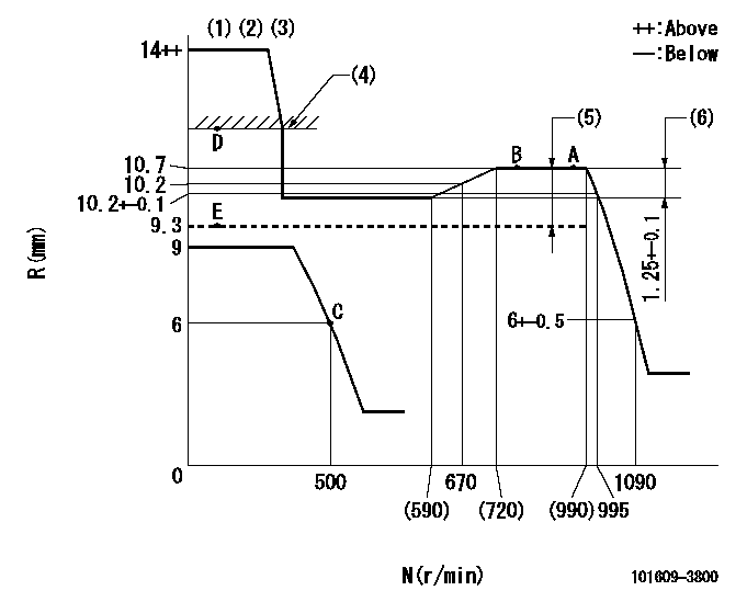
N:Pump speed
R:Rack position (mm)
(1)Target notch: K
(2)Tolerance for racks not indicated: +-0.05mm.
(3)It is not necessary to supply hydraulic pressure because the specification is for the hydraulic ACT normally ON.
(4)RACK LIMIT
(5)Boost compensator stroke: BCL
(6)Rack difference between N = N1 and N = N2
----------
K=17 BCL=(1.4)mm N1=975r/min N2=500r/min
----------
----------
K=17 BCL=(1.4)mm N1=975r/min N2=500r/min
----------
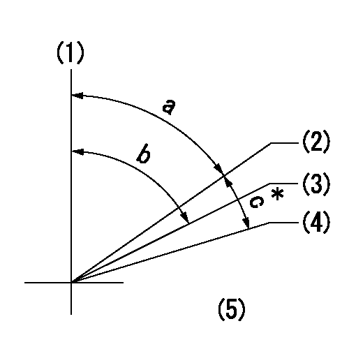
Speed control lever angle
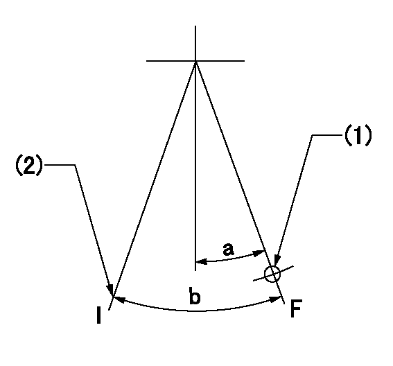
F:Full speed
I:Idle
(1)Use the hole at R = aa
(2)Stopper bolt setting
----------
aa=77mm
----------
a=11deg+-5deg b=35deg+-5deg
----------
aa=77mm
----------
a=11deg+-5deg b=35deg+-5deg
Stop lever angle
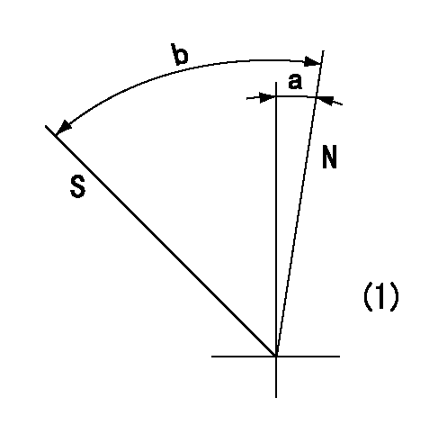
N:Pump normal
S:Stop the pump.
(1)No return spring
----------
----------
a=0deg+-5deg b=53deg+-5deg
----------
----------
a=0deg+-5deg b=53deg+-5deg
0000001501 I/P WITH LOAD PLUNGER ADJ
Adjusting procedure for load plunger equipped pump with RSV (cam lock) governor (see service information S.I. 434 for details).
At cam lift h+-0.01, set the camshaft c deg from the * mark in accordance with the timing adjustment procedure.
2. Align the flyweight's timing tooth position and the lock pin groove and then fully tighten the flyweight to the camshaft. Then, remove the lock pin.
3. Adjust the maximum variation between cylinders and injection quantity.
4. Adjust using the pre-stroke adjusting shim so that the pre-stroke value is the value for 4/4 load (standard point A).
5. After adjusting the pre-stroke, reconfirm that the injection quantity and the maximum variation between cylinders are as specified.
6. At delivery, again fix the flyweight using the lock pin.
----------
h=2.6+-0.01mm c=5deg+-30min
----------
----------
h=2.6+-0.01mm c=5deg+-30min
----------
0000001601 TAMPER PROOF
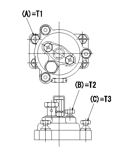
Tamperproofing-equipped boost compensator cover installation procedure
(1)After adjusting the governor and the boost compensator, tighten to the specified torque to break off the bolt heads.
(Tightening torque T = T1 maximum)
(2)After adjusting the governor and the boost compensator, tighten to the specified torque to break off the bolt heads.
(Tightening torque T = T2)
(3)After adjusting the governor and the boost compensator, tighten to the specified torque to break off the bolt heads.
(Tightening torque T = T3)
----------
T1=7.16~9.12N-m(0.73~0.93kgf-m) T2=2.9~4.4N-m(0.3~0.45kgf-m) T3=2.9~4.4N-m(0.3~0.45kgf-m)
----------
----------
T1=7.16~9.12N-m(0.73~0.93kgf-m) T2=2.9~4.4N-m(0.3~0.45kgf-m) T3=2.9~4.4N-m(0.3~0.45kgf-m)
----------
Timing setting
(1)Pump vertical direction
(2)Key groove position for No. 1 cylinder's cam lift h = cc (at BTDC aa).
(3)Key groove position for No. 1 cylinder's beginning of injection (at point A after injection quantity adjustment).
(4)Position of the key groove of the No. 1 cylinder at B.T.D.C. bb (fix the governor flyweight at this position for delivery).
(5)B.T.D.C.: aa
----------
aa=10deg bb=0deg cc=2.6+-0.01mm
----------
a=55deg18min+-3deg b=55deg18min+-3deg13min48sec c=5deg+-30min
----------
aa=10deg bb=0deg cc=2.6+-0.01mm
----------
a=55deg18min+-3deg b=55deg18min+-3deg13min48sec c=5deg+-30min
Have questions with 101609-3800?
Group cross 101609-3800 ZEXEL
Komatsu
101609-3800
9 400 615 917
4063910
INJECTION-PUMP ASSEMBLY
6BTAA5.9
6BTAA5.9
101609-3800
9 400 615 917
6738711540
INJECTION-PUMP ASSEMBLY
6BTAA5.9
6BTAA5.9