Rating:
Information injection-pump assembly
BOSCH
F 019 Z20 032
f019z20032
ZEXEL
101609-3860
1016093860
KOMATSU
4063203
4063203
Compare Prices: .
As an associate, we earn commssions on qualifying purchases through the links below

Agility Auto Parts 4063203 Fuel Filler Neck for 2003-2004 Chevrolet, GMC-Express 1500, 2500, 3500, Savana 1500, 2500, 3500
AGILITY AUTO PARTS Inc. Quick-On Attachment Method || Material - Plastic || Color - Black || No - Bracket, Clamps, Hoses, Hardware Included
AGILITY AUTO PARTS Inc. Quick-On Attachment Method || Material - Plastic || Color - Black || No - Bracket, Clamps, Hoses, Hardware Included

#10 x 1/2" Hex Washer Head Self Drilling Tek Screws, Stainless Steel 410, Full Thread, Plain Finish, Self-Drilling, Quantity 500 by Fastenere
Fastenere Hex washer head self drilling screws have a drill point at the tip of the thread drills its own pilot hole in to metal allowing for quick installation and fastening while saving time and effort with just a single step || Made from an ultra strong stainless steel grade 410 giving them the ability to drill through sheet metal and stainless steel while still being wear resistant and offering a mild chemical corrosion protection; these screws are not intended for use with aluminum as the higher iron content in the fastener will cause embrittlement; 410 Stainless steel is always MAGNETIC due to the higher iron content giving the drilling capabilities || These screws have a hex head that can be driven with a nut driver or socket and can be adjusted with a wrench; the built in flanged washer adds a secure grip to the material being fastened into while also preventing the head from crushing thin metal || The self drilling point also referred to as a tek can self drill metal up to a thickness of 0.090 inches and is best used with a lot of pressure and a slow drill speed; if drilling too fast you could run the risk of over heating the metal drilling tip which could cause it to wear out or warp || Fastenere brand self drilling tapping screws will tap their own thread into the material being screwed into creating a long lasting vibration resistant connection that is the choice for use with corrugated roof siding and sheet metal applications
Fastenere Hex washer head self drilling screws have a drill point at the tip of the thread drills its own pilot hole in to metal allowing for quick installation and fastening while saving time and effort with just a single step || Made from an ultra strong stainless steel grade 410 giving them the ability to drill through sheet metal and stainless steel while still being wear resistant and offering a mild chemical corrosion protection; these screws are not intended for use with aluminum as the higher iron content in the fastener will cause embrittlement; 410 Stainless steel is always MAGNETIC due to the higher iron content giving the drilling capabilities || These screws have a hex head that can be driven with a nut driver or socket and can be adjusted with a wrench; the built in flanged washer adds a secure grip to the material being fastened into while also preventing the head from crushing thin metal || The self drilling point also referred to as a tek can self drill metal up to a thickness of 0.090 inches and is best used with a lot of pressure and a slow drill speed; if drilling too fast you could run the risk of over heating the metal drilling tip which could cause it to wear out or warp || Fastenere brand self drilling tapping screws will tap their own thread into the material being screwed into creating a long lasting vibration resistant connection that is the choice for use with corrugated roof siding and sheet metal applications
Service parts 101609-3860 INJECTION-PUMP ASSEMBLY:
1.
_

5.
AUTOM. ADVANCE MECHANIS
6.
COUPLING PLATE
7.
COUPLING PLATE
8.
_
9.
_
11.
Nozzle and Holder
12.
Open Pre:MPa(Kqf/cm2)
22.0(224)

15.
NOZZLE SET
Include in #1:
101609-3860
as INJECTION-PUMP ASSEMBLY
Include in #2:
104268-1320
as _
Cross reference number
BOSCH
F 019 Z20 032
f019z20032
ZEXEL
101609-3860
1016093860
KOMATSU
4063203
4063203
Zexel num
Bosch num
Firm num
Name
101609-3860
F 019 Z20 032
4063203 KOMATSU
INJECTION-PUMP ASSEMBLY
SAA6D102E K 14BE INJECTION PUMP ASSY PE6A PE
SAA6D102E K 14BE INJECTION PUMP ASSY PE6A PE
101609-3860
F 019 Z20 032
6738711260 KOMATSU
INJECTION-PUMP ASSEMBLY
SAA6D102E K 14BE INJECTION PUMP ASSY PE6A PE
SAA6D102E K 14BE INJECTION PUMP ASSY PE6A PE
Calibration Data:
Adjustment conditions
Test oil
1404 Test oil ISO4113 or {SAEJ967d}
1404 Test oil ISO4113 or {SAEJ967d}
Test oil temperature
degC
40
40
45
Nozzle and nozzle holder
105780-8140
Bosch type code
EF8511/9A
Nozzle
105780-0000
Bosch type code
DN12SD12T
Nozzle holder
105780-2080
Bosch type code
EF8511/9
Opening pressure
MPa
17.2
Opening pressure
kgf/cm2
175
Injection pipe
Outer diameter - inner diameter - length (mm) mm 6-2-600
Outer diameter - inner diameter - length (mm) mm 6-2-600
Overflow valve
131424-3420
Overflow valve opening pressure
kPa
255
221
289
Overflow valve opening pressure
kgf/cm2
2.6
2.25
2.95
Tester oil delivery pressure
kPa
255
255
255
Tester oil delivery pressure
kgf/cm2
2.6
2.6
2.6
Direction of rotation (viewed from drive side)
Right R
Right R
Injection timing adjustment
Direction of rotation (viewed from drive side)
Right R
Right R
Injection order
1-5-3-6-
2-4
Pre-stroke
mm
2.6
2.55
2.65
Rack position
After adjusting injection quantity. R=A
After adjusting injection quantity. R=A
Beginning of injection position
Drive side NO.1
Drive side NO.1
Difference between angles 1
Cal 1-5 deg. 60 59.5 60.5
Cal 1-5 deg. 60 59.5 60.5
Difference between angles 2
Cal 1-3 deg. 120 119.5 120.5
Cal 1-3 deg. 120 119.5 120.5
Difference between angles 3
Cal 1-6 deg. 180 179.5 180.5
Cal 1-6 deg. 180 179.5 180.5
Difference between angles 4
Cyl.1-2 deg. 240 239.5 240.5
Cyl.1-2 deg. 240 239.5 240.5
Difference between angles 5
Cal 1-4 deg. 300 299.5 300.5
Cal 1-4 deg. 300 299.5 300.5
Injection quantity adjustment
Adjusting point
A
Rack position
10.6
Pump speed
r/min
1000
1000
1000
Average injection quantity
mm3/st.
127.5
126.5
128.5
Max. variation between cylinders
%
0
-2.5
2.5
Basic
*
Fixing the lever
*
Boost pressure
kPa
140
140
Boost pressure
mmHg
1050
1050
Injection quantity adjustment_02
Adjusting point
-
Rack position
7.2+-0.5
Pump speed
r/min
450
450
450
Average injection quantity
mm3/st.
13
12
14
Max. variation between cylinders
%
0
-15
15
Fixing the rack
*
Boost pressure
kPa
0
0
0
Boost pressure
mmHg
0
0
0
Remarks
Adjust only variation between cylinders; adjust governor according to governor specifications.
Adjust only variation between cylinders; adjust governor according to governor specifications.
Injection quantity adjustment_03
Adjusting point
F
Rack position
11.3++
Pump speed
r/min
100
100
100
Average injection quantity
mm3/st.
105
100
110
Fixing the lever
*
Boost pressure
kPa
0
0
0
Boost pressure
mmHg
0
0
0
Rack limit
*
Boost compensator adjustment
Pump speed
r/min
750
750
750
Rack position
8.9
Boost pressure
kPa
20
13.3
26.7
Boost pressure
mmHg
150
100
200
Boost compensator adjustment_02
Pump speed
r/min
750
750
750
Rack position
10.2
Boost pressure
kPa
80
76
84
Boost pressure
mmHg
600
570
630
Boost compensator adjustment_03
Pump speed
r/min
750
750
750
Rack position
11.1
Boost pressure
kPa
127
127
127
Boost pressure
mmHg
950
950
950
Test data Ex:
Governor adjustment
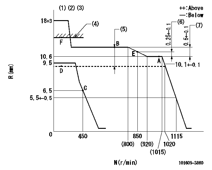
N:Pump speed
R:Rack position (mm)
(1)Target notch: K
(2)Tolerance for racks not indicated: +-0.05mm.
(3)Because the specifications are for the hydraulic actuator to be normally ON, it is not necessary to supply hydraulic pressure. (The eye bolt, however, must be installed.)
(4)RACK LIMIT
(5)Boost compensator stroke: BCL
(6)Rack difference from N = N1
(7)Rack difference between N = N2 and N = N3
----------
K=10 BCL=2.2+-0.1mm N1=1000r/min N2=1000r/min N3=750r/min
----------
----------
K=10 BCL=2.2+-0.1mm N1=1000r/min N2=1000r/min N3=750r/min
----------
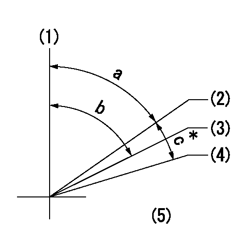
Speed control lever angle
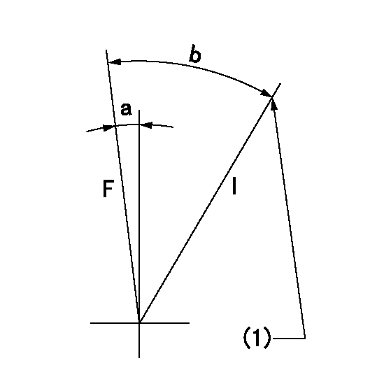
F:Full speed
I:Idle
(1)Stopper bolt setting
----------
----------
a=11deg+-5deg b=30deg+-5deg
----------
----------
a=11deg+-5deg b=30deg+-5deg
Stop lever angle
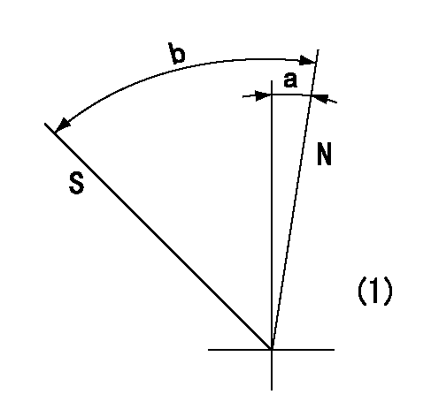
N:Pump normal
S:Stop the pump.
(1)No return spring
----------
----------
a=0deg+-5deg b=53deg+-5deg
----------
----------
a=0deg+-5deg b=53deg+-5deg
0000001501 TAMPER PROOF
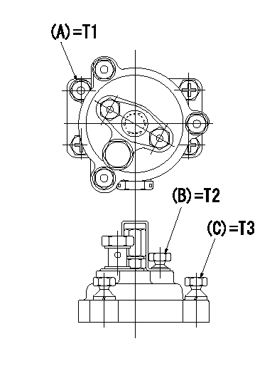
Tamperproofing-equipped boost compensator cover installation procedure
(1)After adjusting the governor and the boost compensator, tighten to the specified torque to break off the bolt heads.
(Tightening torque T = T1 maximum)
(2)After adjusting the governor and the boost compensator, tighten to the specified torque to break off the bolt heads.
(Tightening torque T = T2)
(3)After adjusting the governor and the boost compensator, tighten to the specified torque to break off the bolt heads.
(Tightening torque T = T3)
----------
T1=7.16~9.12N-m(0.73~0.93kgf-m) T2=2.9~4.4N-m(0.3~0.45kgf-m) T3=2.9~4.4N-m(0.3~0.45kgf-m)
----------
----------
T1=7.16~9.12N-m(0.73~0.93kgf-m) T2=2.9~4.4N-m(0.3~0.45kgf-m) T3=2.9~4.4N-m(0.3~0.45kgf-m)
----------
0000001601 I/P WITH LOAD PLUNGER ADJ
Adjusting procedure for load plunger equipped pump with RSV (cam lock) governor (see service information S.I. 434 for details).
At cam lift h+-0.01, set the camshaft c deg from the * mark in accordance with the timing adjustment procedure.
2. Align the flyweight's timing tooth position and the lock pin groove and then fully tighten the flyweight to the camshaft. Then, remove the lock pin.
3. Adjust the maximum variation between cylinders and injection quantity.
4. Adjust using the pre-stroke adjusting shim so that the pre-stroke value is the value for 4/4 load (standard point A).
5. After adjusting the pre-stroke, reconfirm that the injection quantity and the maximum variation between cylinders are as specified.
6. At delivery, again fix the flyweight using the lock pin.
----------
h=2.6mm c=5deg15min+-30min
----------
----------
h=2.6mm c=5deg15min+-30min
----------
Timing setting
(1)Pump vertical direction
(2)Key groove position for No. 1 cylinder's cam lift h = cc (at BTDC aa).
(3)Key groove position for No. 1 cylinder's beginning of injection (at point A after injection quantity adjustment).
(4)Position of the key groove of the No. 1 cylinder at B.T.D.C. bb (fix the governor flyweight at this position for delivery).
(5)B.T.D.C.: aa
----------
aa=10.5deg bb=0deg cc=2.6+-0.01mm
----------
a=55deg18min+-3deg b=55deg18min+-3deg13min48sec c=5deg15min+-30min
----------
aa=10.5deg bb=0deg cc=2.6+-0.01mm
----------
a=55deg18min+-3deg b=55deg18min+-3deg13min48sec c=5deg15min+-30min
Have questions with 101609-3860?
Group cross 101609-3860 ZEXEL
Komatsu
Komatsu
Komatsu
101609-3860
F 019 Z20 032
4063203
INJECTION-PUMP ASSEMBLY
SAA6D102E
SAA6D102E
101609-3860
F 019 Z20 032
6738711260
INJECTION-PUMP ASSEMBLY
SAA6D102E
SAA6D102E