Rating:
Information injection-pump assembly
ZEXEL
101608-1510
1016081510
Cross reference number
ZEXEL
101608-1510
1016081510
Zexel num
Bosch num
Firm num
Name
101608-1510
INJECTION-PUMP ASSEMBLY
14BE PE6A PE
14BE PE6A PE
Calibration Data:
Adjustment conditions
Test oil
1404 Test oil ISO4113 or {SAEJ967d}
1404 Test oil ISO4113 or {SAEJ967d}
Test oil temperature
degC
40
40
45
Nozzle and nozzle holder
105780-8140
Bosch type code
EF8511/9A
Nozzle
105780-0000
Bosch type code
DN12SD12T
Nozzle holder
105780-2080
Bosch type code
EF8511/9
Opening pressure
MPa
17.2
Opening pressure
kgf/cm2
175
Injection pipe
Outer diameter - inner diameter - length (mm) mm 6-2-600
Outer diameter - inner diameter - length (mm) mm 6-2-600
Overflow valve
131424-5520
Overflow valve opening pressure
kPa
255
221
289
Overflow valve opening pressure
kgf/cm2
2.6
2.25
2.95
Tester oil delivery pressure
kPa
157
157
157
Tester oil delivery pressure
kgf/cm2
1.6
1.6
1.6
Direction of rotation (viewed from drive side)
Left L
Left L
Injection timing adjustment
Direction of rotation (viewed from drive side)
Left L
Left L
Injection order
1-5-3-6-
2-4
Pre-stroke
mm
3.3
3.25
3.35
Beginning of injection position
Governor side NO.1
Governor side NO.1
Difference between angles 1
Cal 1-5 deg. 60 59.5 60.5
Cal 1-5 deg. 60 59.5 60.5
Difference between angles 2
Cal 1-3 deg. 120 119.5 120.5
Cal 1-3 deg. 120 119.5 120.5
Difference between angles 3
Cal 1-6 deg. 180 179.5 180.5
Cal 1-6 deg. 180 179.5 180.5
Difference between angles 4
Cyl.1-2 deg. 240 239.5 240.5
Cyl.1-2 deg. 240 239.5 240.5
Difference between angles 5
Cal 1-4 deg. 300 299.5 300.5
Cal 1-4 deg. 300 299.5 300.5
Injection quantity adjustment
Adjusting point
-
Rack position
11.4
Pump speed
r/min
700
700
700
Each cylinder's injection qty
mm3/st.
54.5
52.9
56.1
Basic
*
Fixing the rack
*
Standard for adjustment of the maximum variation between cylinders
*
Injection quantity adjustment_02
Adjusting point
D
Rack position
8.7+-0.5
Pump speed
r/min
500
500
500
Each cylinder's injection qty
mm3/st.
7.6
6.5
8.7
Fixing the rack
*
Standard for adjustment of the maximum variation between cylinders
*
Injection quantity adjustment_03
Adjusting point
A
Rack position
R1(11.4)
Pump speed
r/min
700
700
700
Average injection quantity
mm3/st.
54.5
53.5
55.5
Basic
*
Fixing the lever
*
Injection quantity adjustment_04
Adjusting point
B
Rack position
R1+0.5
Pump speed
r/min
1450
1450
1450
Average injection quantity
mm3/st.
84
80
88
Fixing the lever
*
Injection quantity adjustment_05
Adjusting point
C
Rack position
R1(11.4)
Pump speed
r/min
600
600
600
Average injection quantity
mm3/st.
48.5
44.5
52.5
Fixing the lever
*
Injection quantity adjustment_06
Adjusting point
I
Rack position
-
Pump speed
r/min
100
100
100
Average injection quantity
mm3/st.
73
63
83
Fixing the lever
*
Rack limit
*
Injection quantity adjustment_07
Adjusting point
H
Rack position
9.5+-0.5
Pump speed
r/min
275
275
275
Each cylinder's injection qty
mm3/st.
8.7
7.4
10
Fixing the rack
*
Remarks
(check)
(check)
Timer adjustment
Pump speed
r/min
900--
Advance angle
deg.
0
0
0
Remarks
Start
Start
Timer adjustment_02
Pump speed
r/min
850
Advance angle
deg.
0.5
Timer adjustment_03
Pump speed
r/min
1200
Advance angle
deg.
2.7
2.2
3.2
Timer adjustment_04
Pump speed
r/min
1500
Advance angle
deg.
5
4.5
5.5
Remarks
Finish
Finish
Test data Ex:
Governor adjustment
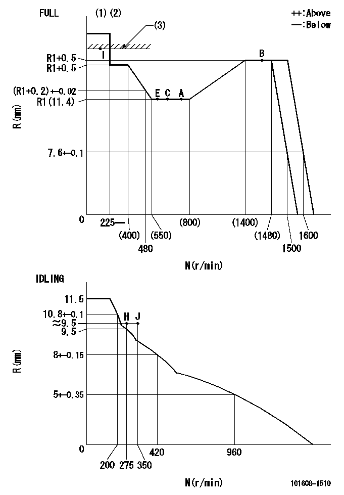
N:Pump speed
R:Rack position (mm)
(1)Torque cam stamping: T1
(2)Tolerance for racks not indicated: +-0.05mm.
(3)RACK LIMIT
----------
T1=J32
----------
----------
T1=J32
----------
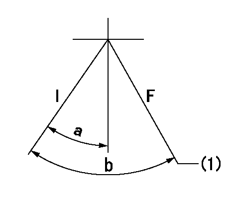
Speed control lever angle
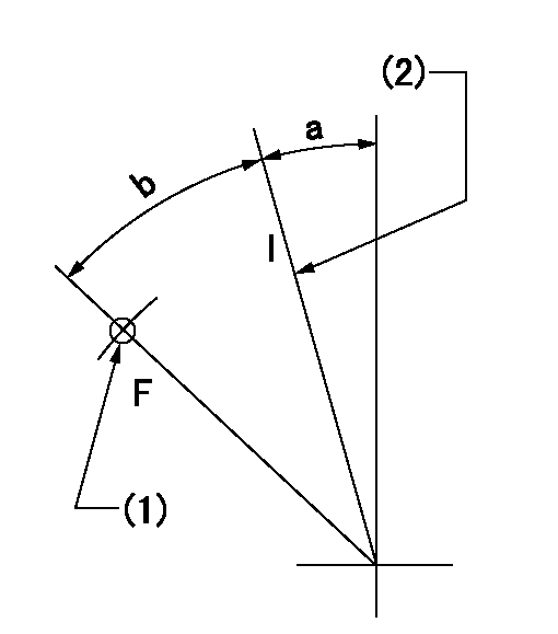
F:Full speed
I:Idle
(1)Use the hole at R = aa
(2)Stopper bolt set position 'H'
----------
aa=29mm
----------
a=18.5deg+-5deg b=41deg+-3deg
----------
aa=29mm
----------
a=18.5deg+-5deg b=41deg+-3deg
Stop lever angle
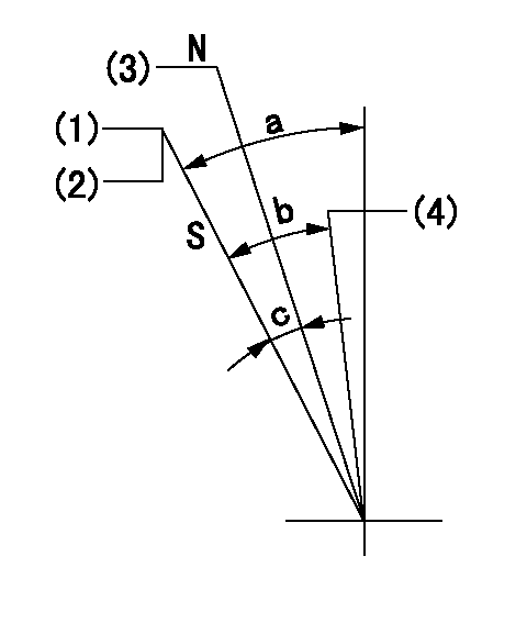
N:Engine manufacturer's normal use
S:Stop the pump.
(1)Set the stopper bolt at pump speed = aa and rack position = bb (non-injection rack position). Confirm non-injection.
(2)After setting the stopper bolt, confirm non-injection at speed cc. Rack position = dd (non-injection rack position).
(3)Rack position = approximately ee (speed lever full, speed = ff).
(4)Free (at delivery)
----------
aa=1450r/min bb=4.7-0.5mm cc=275r/min dd=(6.3)mm ee=15mm ff=0r/min
----------
a=38.5deg+-5deg b=(29deg) c=17deg+-5deg
----------
aa=1450r/min bb=4.7-0.5mm cc=275r/min dd=(6.3)mm ee=15mm ff=0r/min
----------
a=38.5deg+-5deg b=(29deg) c=17deg+-5deg
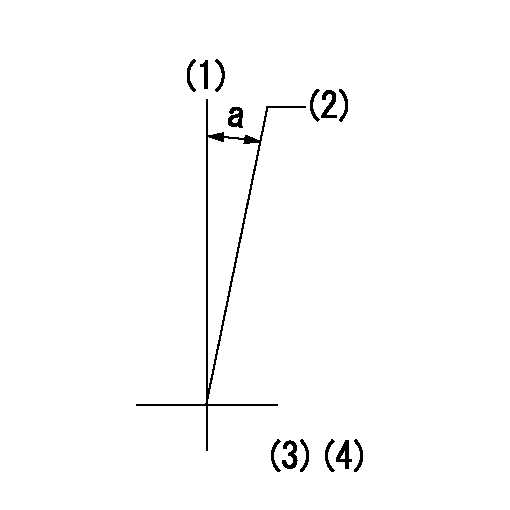
0000001201
I:Idle
F:At operation, hold it in the full speed position.
(1)At rack position aa and pump speed bb, set the stopper bolt. (After setting it, apply red paint.)
----------
aa=7.6+-0.1mm bb=1500r/min
----------
a=15deg+-5deg b=(36deg)+-3deg
----------
aa=7.6+-0.1mm bb=1500r/min
----------
a=15deg+-5deg b=(36deg)+-3deg
Timing setting
(1)Pump vertical direction
(2)Position of timer's tooth at No 1 cylinder's beginning of injection
(3)B.T.D.C.: aa
(4)-
----------
aa=16deg
----------
a=(1deg)
----------
aa=16deg
----------
a=(1deg)
Have questions with 101608-1510?
Group cross 101608-1510 ZEXEL
Mitsubishi
101608-1510
INJECTION-PUMP ASSEMBLY