
Rating:
Information injection-pump assembly
ZEXEL
106971-0650
1069710650
Service parts 106971-0650 INJECTION-PUMP ASSEMBLY:
1.
_
6.
COUPLING PLATE
7.
COUPLING PLATE
8.
_
9.
_
11.
Nozzle and Holder
1660097013
12.
Open Pre:MPa(Kqf/cm2)
22.6(230)
15.
NOZZLE SET
Include in #1:
106971-0650
as INJECTION-PUMP ASSEMBLY
Cross reference number
ZEXEL
106971-0650
1069710650
Zexel num
Bosch num
Firm num
Name
106971-0650
INJECTION-PUMP ASSEMBLY
Calibration Data:
Adjustment conditions
Test oil
1404 Test oil ISO4113 or {SAEJ967d}
1404 Test oil ISO4113 or {SAEJ967d}
Test oil temperature
degC
40
40
45
Nozzle and nozzle holder
105780-8140
Bosch type code
EF8511/9A
Nozzle
105780-0000
Bosch type code
DN12SD12T
Nozzle holder
105780-2080
Bosch type code
EF8511/9
Opening pressure
MPa
17.2
Opening pressure
kgf/cm2
175
Injection pipe
Outer diameter - inner diameter - length (mm) mm 8-3-600
Outer diameter - inner diameter - length (mm) mm 8-3-600
Overflow valve opening pressure
kPa
157
123
191
Overflow valve opening pressure
kgf/cm2
1.6
1.25
1.95
Tester oil delivery pressure
kPa
157
157
157
Tester oil delivery pressure
kgf/cm2
1.6
1.6
1.6
Direction of rotation (viewed from drive side)
Right R
Right R
Injection timing adjustment
Direction of rotation (viewed from drive side)
Right R
Right R
Injection order
10-9-4-3
-6-5-8-7
-2-1
Pre-stroke
mm
3
2.95
3.05
Beginning of injection position
Governor side NO.1
Governor side NO.1
Difference between angles 1
Cal 10-9 deg. 45 44.5 45.5
Cal 10-9 deg. 45 44.5 45.5
Difference between angles 2
Cal 10-4 deg. 72 71.5 72.5
Cal 10-4 deg. 72 71.5 72.5
Difference between angles 3
Cal 10-3 deg. 117 116.5 117.5
Cal 10-3 deg. 117 116.5 117.5
Difference between angles 4
Cal 10-6 deg. 144 143.5 144.5
Cal 10-6 deg. 144 143.5 144.5
Difference between angles 5
Cal 10-5 deg. 189 188.5 189.5
Cal 10-5 deg. 189 188.5 189.5
Difference between angles 6
Cal 10-8 deg. 216 215.5 216.5
Cal 10-8 deg. 216 215.5 216.5
Difference between angles 7
Cal 10-7 deg. 261 260.5 261.5
Cal 10-7 deg. 261 260.5 261.5
Difference between angles 8
Cal 10-2 deg. 288 287.5 288.5
Cal 10-2 deg. 288 287.5 288.5
Difference between angles 9
Cal 10-1 deg. 333 332.5 333.5
Cal 10-1 deg. 333 332.5 333.5
Injection quantity adjustment
Adjusting point
A
Rack position
12.7
Pump speed
r/min
775
775
775
Average injection quantity
mm3/st.
160.1
159.1
161.1
Max. variation between cylinders
%
0
-4
4
Basic
*
Fixing the lever
*
Boost pressure
kPa
82.6
82.6
Boost pressure
mmHg
620
620
Injection quantity adjustment_02
Adjusting point
B
Rack position
12.1
Pump speed
r/min
1000
1000
1000
Average injection quantity
mm3/st.
141.8
137.8
145.8
Max. variation between cylinders
%
0
-4
4
Fixing the lever
*
Boost pressure
kPa
82.6
82.6
Boost pressure
mmHg
620
620
Injection quantity adjustment_03
Adjusting point
C
Rack position
11.1
Pump speed
r/min
500
500
500
Average injection quantity
mm3/st.
124.1
120.1
128.1
Max. variation between cylinders
%
0
-4
4
Fixing the lever
*
Boost pressure
kPa
0
0
0
Boost pressure
mmHg
0
0
0
Injection quantity adjustment_04
Adjusting point
D
Rack position
6.9+-0.5
Pump speed
r/min
340
340
340
Average injection quantity
mm3/st.
15.3
13.3
17.3
Max. variation between cylinders
%
0
-10
10
Fixing the rack
*
Boost pressure
kPa
0
0
0
Boost pressure
mmHg
0
0
0
Boost compensator adjustment
Pump speed
r/min
600
600
600
Rack position
11.1
Boost pressure
kPa
33.3
28
38.6
Boost pressure
mmHg
250
210
290
Boost compensator adjustment_02
Pump speed
r/min
600
600
600
Rack position
12.7
Boost pressure
kPa
73.3
70.6
76
Boost pressure
mmHg
550
530
570
Timer adjustment
Pump speed
r/min
750--
Advance angle
deg.
0
0
0
Remarks
Start
Start
Timer adjustment_02
Pump speed
r/min
700
Advance angle
deg.
0.5
Timer adjustment_03
Pump speed
r/min
1000
Advance angle
deg.
1.5
1
2
Timer adjustment_04
Pump speed
r/min
-
Advance angle
deg.
3.5
3.5
3.5
Remarks
Measure the actual speed, stop
Measure the actual speed, stop
Test data Ex:
Governor adjustment
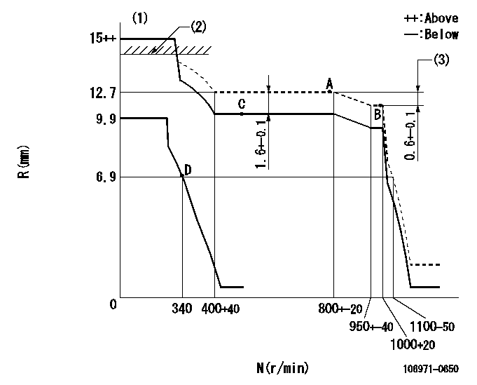
N:Pump speed
R:Rack position (mm)
(1)Target notch: K
(2)RACK LIMIT: RAL
(3)Rack difference between N = N1 and N = N2
----------
K=10 RAL=14.5+-0.1mm N1=1000r/min N2=775r/min
----------
----------
K=10 RAL=14.5+-0.1mm N1=1000r/min N2=775r/min
----------
Speed control lever angle
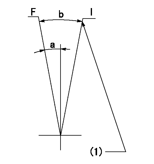
F:Full speed
I:Idle
(1)Stopper bolt setting
----------
----------
a=9deg+-5deg b=29deg+-5deg
----------
----------
a=9deg+-5deg b=29deg+-5deg
Stop lever angle
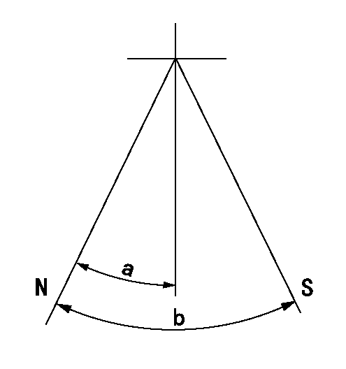
N:Pump normal
S:Stop the pump.
----------
----------
a=16.5deg+-5deg b=50deg+-5deg
----------
----------
a=16.5deg+-5deg b=50deg+-5deg
Timing setting
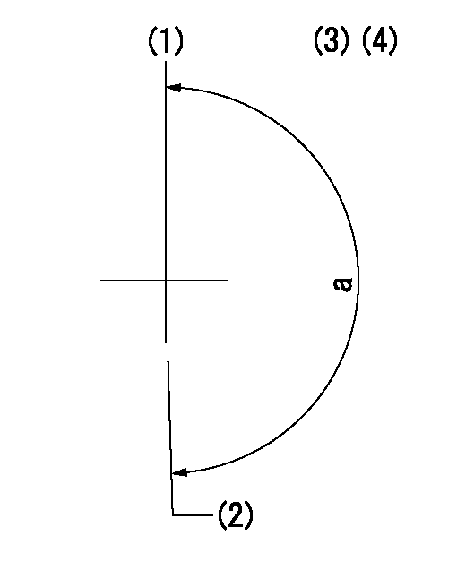
(1)Pump vertical direction
(2)Position of the gear's standard threaded installation hole at the start of injection for the No. 10 cylinder.
(3)-
(4)-
----------
----------
a=(50deg)
----------
----------
a=(50deg)
Have questions with 106971-0650?
Group cross 106971-0650 ZEXEL
Nissan-Diesel
Nissan-Diesel
Nissan-Diesel
Nissan-Diesel
106971-0650
INJECTION-PUMP ASSEMBLY