
Rating:
Information injection-pump assembly
ZEXEL
106871-3220
1068713220
HINO
220002143B
220002143b
Service parts 106871-3220 INJECTION-PUMP ASSEMBLY:
1.
_
7.
COUPLING PLATE
8.
_
9.
_
11.
Nozzle and Holder
23600-1212
12.
Open Pre:MPa(Kqf/cm2)
21.6{220}
15.
NOZZLE SET
Include in #1:
106871-3220
as INJECTION-PUMP ASSEMBLY
Cross reference number
ZEXEL
106871-3220
1068713220
HINO
220002143B
220002143b
Zexel num
Bosch num
Firm num
Name
Calibration Data:
Adjustment conditions
Test oil
1404 Test oil ISO4113 or {SAEJ967d}
1404 Test oil ISO4113 or {SAEJ967d}
Test oil temperature
degC
40
40
45
Nozzle and nozzle holder
105780-8140
Bosch type code
EF8511/9A
Nozzle
105780-0000
Bosch type code
DN12SD12T
Nozzle holder
105780-2080
Bosch type code
EF8511/9
Opening pressure
MPa
17.2
Opening pressure
kgf/cm2
175
Injection pipe
Outer diameter - inner diameter - length (mm) mm 8-3-600
Outer diameter - inner diameter - length (mm) mm 8-3-600
Overflow valve
134424-1020
Overflow valve opening pressure
kPa
127
107
147
Overflow valve opening pressure
kgf/cm2
1.3
1.1
1.5
Tester oil delivery pressure
kPa
157
157
157
Tester oil delivery pressure
kgf/cm2
1.6
1.6
1.6
Direction of rotation (viewed from drive side)
Right R
Right R
Injection timing adjustment
Direction of rotation (viewed from drive side)
Right R
Right R
Injection order
1-8-6-2-
7-5-4-3
Pre-stroke
mm
4
3.94
4
Beginning of injection position
Drive side NO.1
Drive side NO.1
Difference between angles 1
Cal 1-8 deg. 45 44.75 45.25
Cal 1-8 deg. 45 44.75 45.25
Difference between angles 2
Cal 1-6 deg. 90 89.75 90.25
Cal 1-6 deg. 90 89.75 90.25
Difference between angles 3
Cyl.1-2 deg. 135 134.75 135.25
Cyl.1-2 deg. 135 134.75 135.25
Difference between angles 4
Cal 1-7 deg. 180 179.75 180.25
Cal 1-7 deg. 180 179.75 180.25
Difference between angles 5
Cal 1-5 deg. 225 224.75 225.25
Cal 1-5 deg. 225 224.75 225.25
Difference between angles 6
Cal 1-4 deg. 270 269.75 270.25
Cal 1-4 deg. 270 269.75 270.25
Difference between angles 7
Cal 1-3 deg. 315 314.75 315.25
Cal 1-3 deg. 315 314.75 315.25
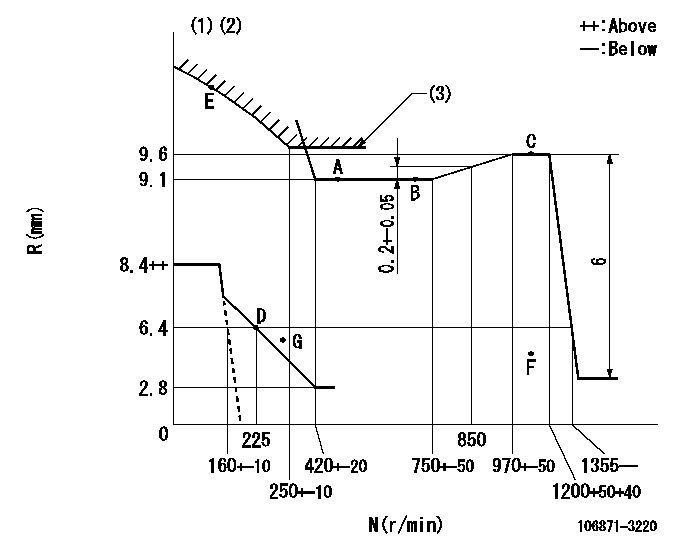
Injection quantity adjustment
Adjusting point
A
Rack position
9.1
Pump speed
r/min
500
500
500
Average injection quantity
mm3/st.
109
106
112
Max. variation between cylinders
%
0
-4
4
Fixing the lever
*
Injection quantity adjustment_02
Adjusting point
B
Rack position
9.1
Pump speed
r/min
700
700
700
Average injection quantity
mm3/st.
110.5
108.5
112.5
Max. variation between cylinders
%
0
-2
2
Basic
*
Fixing the lever
*
Injection quantity adjustment_03
Adjusting point
C
Rack position
9.6
Pump speed
r/min
1200
1200
1200
Average injection quantity
mm3/st.
125.5
122.5
128.5
Max. variation between cylinders
%
0
-4
4
Fixing the lever
*
Injection quantity adjustment_04
Adjusting point
D
Rack position
6.4+-0.5
Pump speed
r/min
225
225
225
Average injection quantity
mm3/st.
13.7
10.7
16.7
Max. variation between cylinders
%
0
-15
15
Fixing the rack
*
Injection quantity adjustment_05
Adjusting point
E
Rack position
-
Pump speed
r/min
50
50
50
Average injection quantity
mm3/st.
115
115
135
Fixing the lever
*
Remarks
After startup boost setting
After startup boost setting
Injection quantity adjustment_06
Adjusting point
F
Rack position
-
Pump speed
r/min
1000
1000
1000
Average injection quantity
mm3/st.
0
0
0
Fixing the lever
*
Timer adjustment
Pump speed
r/min
950
Advance angle
deg.
0.4
Timer adjustment_02
Pump speed
r/min
1000
Advance angle
deg.
0.7
0.2
1.2
Timer adjustment_03
Pump speed
r/min
1050
Advance angle
deg.
1.6
1.1
2.1
Timer adjustment_04
Pump speed
r/min
1125
Advance angle
deg.
3
2.7
3.3
Remarks
Finish
Finish
Test data Ex:
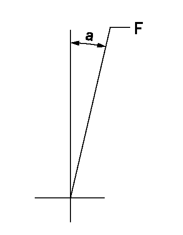
Governor adjustment
N:Pump speed
R:Rack position (mm)
(1)Beginning of damper spring operation: DL
(2)Set idle at point G (N = N1, R = R1) and confirm that the fuel injection quantity at point F (N = N2) does not exceed Q1.
(3)Excess fuel setting for starting: SXL
----------
DL=5.4-0.2mm N1=300r/min R1=5.4mm N2=1000r/min Q1=0mm3/st SXL=10.2+0.2mm
----------
----------
DL=5.4-0.2mm N1=300r/min R1=5.4mm N2=1000r/min Q1=0mm3/st SXL=10.2+0.2mm
----------
Speed control lever angle
F:Full speed
----------
----------
a=4deg+-5deg
----------
----------
a=4deg+-5deg
0000000901
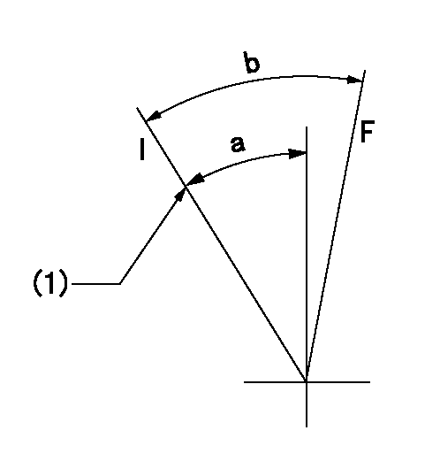
F:Full load
I:Idle
(1)Stopper bolt setting
----------
----------
a=34deg+-5deg b=34deg+-3deg
----------
----------
a=34deg+-5deg b=34deg+-3deg
Stop lever angle
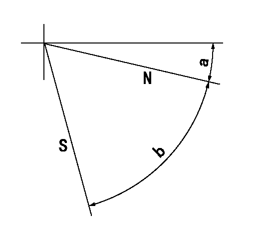
N:Pump normal
S:Stop the pump.
----------
----------
a=15deg+-5deg b=64deg+-5deg
----------
----------
a=15deg+-5deg b=64deg+-5deg
0000001501 MICRO SWITCH
Switch adjustment
Adjust the bolt so that the lower lever position is obtained when the switch is turned ON.
(1)Speed N1
(2)Rack position Ra
----------
N1=325-25r/min Ra=6.4mm
----------
----------
N1=325-25r/min Ra=6.4mm
----------