Rating:
Information injection-pump assembly
BOSCH
9 400 617 428
9400617428
ZEXEL
106676-2080
1066762080
MITSUBISHI
ME158580
me158580
Service parts 106676-2080 INJECTION-PUMP ASSEMBLY:
1.
_
7.
COUPLING PLATE
8.
_
9.
_
11.
Nozzle and Holder
12.
Open Pre:MPa(Kqf/cm2)
17.7{180}/21.6{220}

15.
NOZZLE SET
Include in #1:
106676-2080
as INJECTION-PUMP ASSEMBLY
Cross reference number
BOSCH
9 400 617 428
9400617428
ZEXEL
106676-2080
1066762080
MITSUBISHI
ME158580
me158580
Zexel num
Bosch num
Firm num
Name
106676-2080
9 400 617 428
ME158580 MITSUBISHI
INJECTION-PUMP ASSEMBLY
6D24TC K 14CA INJECTION PUMP ASSY PE6P,6PD PE
6D24TC K 14CA INJECTION PUMP ASSY PE6P,6PD PE
Calibration Data:
Adjustment conditions
Test oil
1404 Test oil ISO4113 or {SAEJ967d}
1404 Test oil ISO4113 or {SAEJ967d}
Test oil temperature
degC
40
40
45
Nozzle and nozzle holder
105780-8140
Bosch type code
EF8511/9A
Nozzle
105780-0000
Bosch type code
DN12SD12T
Nozzle holder
105780-2080
Bosch type code
EF8511/9
Opening pressure
MPa
17.2
Opening pressure
kgf/cm2
175
Injection pipe
Outer diameter - inner diameter - length (mm) mm 8-3-600
Outer diameter - inner diameter - length (mm) mm 8-3-600
Overflow valve
131424-4620
Overflow valve opening pressure
kPa
255
221
289
Overflow valve opening pressure
kgf/cm2
2.6
2.25
2.95
Tester oil delivery pressure
kPa
157
157
157
Tester oil delivery pressure
kgf/cm2
1.6
1.6
1.6
Direction of rotation (viewed from drive side)
Right R
Right R
Injection timing adjustment
Direction of rotation (viewed from drive side)
Right R
Right R
Injection order
1-5-3-6-
2-4
Pre-stroke
mm
4.8
4.75
4.85
Beginning of injection position
Governor side NO.1
Governor side NO.1
Difference between angles 1
Cal 1-5 deg. 60 59.5 60.5
Cal 1-5 deg. 60 59.5 60.5
Difference between angles 2
Cal 1-3 deg. 120 119.5 120.5
Cal 1-3 deg. 120 119.5 120.5
Difference between angles 3
Cal 1-6 deg. 180 179.5 180.5
Cal 1-6 deg. 180 179.5 180.5
Difference between angles 4
Cyl.1-2 deg. 240 239.5 240.5
Cyl.1-2 deg. 240 239.5 240.5
Difference between angles 5
Cal 1-4 deg. 300 299.5 300.5
Cal 1-4 deg. 300 299.5 300.5
Injection quantity adjustment
Adjusting point
A
Rack position
10.6
Pump speed
r/min
1000
1000
1000
Average injection quantity
mm3/st.
168.5
165.5
171.5
Max. variation between cylinders
%
0
-3
3
Basic
*
Fixing the lever
*
Boost pressure
kPa
36
36
Boost pressure
mmHg
270
270
Injection quantity adjustment_02
Adjusting point
B
Rack position
6+-0.5
Pump speed
r/min
425
425
425
Average injection quantity
mm3/st.
8
5.4
10.6
Max. variation between cylinders
%
0
-15
15
Fixing the rack
*
Boost pressure
kPa
0
0
0
Boost pressure
mmHg
0
0
0
Injection quantity adjustment_03
Adjusting point
D
Rack position
-
Pump speed
r/min
100
100
100
Average injection quantity
mm3/st.
195
175
215
Fixing the lever
*
Boost pressure
kPa
0
0
0
Boost pressure
mmHg
0
0
0
Rack limit
*
Boost compensator adjustment
Pump speed
r/min
600
600
600
Rack position
R1-1.65
Boost pressure
kPa
4
2.7
5.3
Boost pressure
mmHg
30
20
40
Boost compensator adjustment_02
Pump speed
r/min
600
600
600
Rack position
R1-0.25
Boost pressure
kPa
20
13.3
26.7
Boost pressure
mmHg
150
100
200
Boost compensator adjustment_03
Pump speed
r/min
600
600
600
Rack position
R1(10.6)
Boost pressure
kPa
22.7
22.7
22.7
Boost pressure
mmHg
170
170
170
Timer adjustment
Pump speed
r/min
825--
Advance angle
deg.
0
0
0
Remarks
Start
Start
Timer adjustment_02
Pump speed
r/min
775
Advance angle
deg.
0.5
Timer adjustment_03
Pump speed
r/min
975
Advance angle
deg.
1
0.5
1.5
Remarks
Finish
Finish
Test data Ex:
Governor adjustment
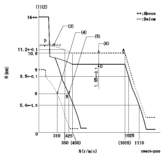
N:Pump speed
R:Rack position (mm)
(1)Notch fixed: K
(2)Tolerance for racks not indicated: +-0.05mm.
(3)RACK LIMIT
(4)Set idle sub-spring
(5)Main spring setting
(6)Boost compensator stroke
----------
K=11
----------
----------
K=11
----------
Speed control lever angle
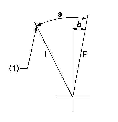
F:Full speed
I:Idle
(1)Stopper bolt setting
----------
----------
a=(20deg)+-5deg b=(4deg)+-5deg
----------
----------
a=(20deg)+-5deg b=(4deg)+-5deg
Stop lever angle
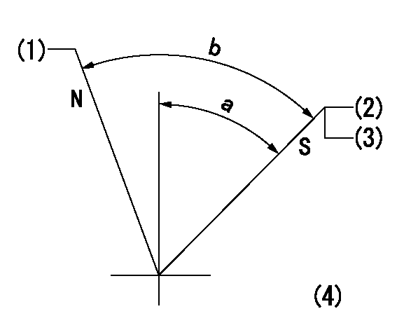
N:Pump normal
S:Stop the pump.
(1)Set the outer screw where it contacts the inside (seal at delivery)
(2)Pump speed aa and rack position bb (to be sealed at delivery)
(3)Stopper bolt setting
(4)No return spring
----------
aa=0r/min bb=1-0.5mm
----------
a=55deg+-5deg b=70deg+-5deg
----------
aa=0r/min bb=1-0.5mm
----------
a=55deg+-5deg b=70deg+-5deg
Timing setting

(1)Pump vertical direction
(2)Coupling's key groove position at No 1 cylinder's beginning of injection
(3)B.T.D.C.: aa
(4)-
----------
aa=13deg
----------
a=(7deg)
----------
aa=13deg
----------
a=(7deg)
Have questions with 106676-2080?
Group cross 106676-2080 ZEXEL
Mitsubishi
Mitsubishi
Mitsubishi
Mitsubishi
Mitsubishi
Mitsubishi
106676-2080
9 400 617 428
ME158580
INJECTION-PUMP ASSEMBLY
6D24TC
6D24TC