Rating:
Information injection-pump assembly
ZEXEL
106675-4510
1066754510
KOMATSU
6152721260
6152721260
Compare Prices: .
As an associate, we earn commssions on qualifying purchases through the links below

106675-4510 Diesel Fuel Injection Pump Model: (6152-72-1260). Adapted To Engine SAA6D125E-2
Thcbme Other Part Number: 6152-72-1260 || Diesel Fuel Injection Pump, Model: 106675-4510 (6152-72-1260). Adapted To Engine SAA6D125E-2 || High efficiency: for a stable and efficient fuel supply || Ideal replacement: Precision engineered to match specific vehicles || Ensure fit: To make sure this part fits your exact vehicle
Thcbme Other Part Number: 6152-72-1260 || Diesel Fuel Injection Pump, Model: 106675-4510 (6152-72-1260). Adapted To Engine SAA6D125E-2 || High efficiency: for a stable and efficient fuel supply || Ideal replacement: Precision engineered to match specific vehicles || Ensure fit: To make sure this part fits your exact vehicle

$2,952.28
23 Oct 2023
0.0022[0.00] Pounds
CN: ChengJiaHui Auto par
Diesel Fuel Injection Pump, Model: 106675-4510 (6152-72-1260). Adapted To Engine SAA6D125E-2
TINYME Other Part Number: 6152-72-1260 || Diesel Fuel Injection Pump, Model: 106675-4510 (6152-72-1260). Adapted To Engine SAA6D125E-2 || ✍ Our fuel pump efficiently transfers fuel to the engine, which will enhance your vehicle's performance and fuel efficiency. || ✍ With anti-clogging design, it can effectively filter impurities and particles in the oil to ensure that the fuel flows smoothly. This will extend the life of the fuel pump and reduce the frequency of maintenance. || ✍ A simple installation procedure also ensures that it will remain efficient over a long period of time, eliminating the need for frequent replacement.
TINYME Other Part Number: 6152-72-1260 || Diesel Fuel Injection Pump, Model: 106675-4510 (6152-72-1260). Adapted To Engine SAA6D125E-2 || ✍ Our fuel pump efficiently transfers fuel to the engine, which will enhance your vehicle's performance and fuel efficiency. || ✍ With anti-clogging design, it can effectively filter impurities and particles in the oil to ensure that the fuel flows smoothly. This will extend the life of the fuel pump and reduce the frequency of maintenance. || ✍ A simple installation procedure also ensures that it will remain efficient over a long period of time, eliminating the need for frequent replacement.
Service parts 106675-4510 INJECTION-PUMP ASSEMBLY:
1.
_

5.
AUTOM. ADVANCE MECHANIS
6.
COUPLING PLATE
8.
_
9.
_
11.
Nozzle and Holder
6152-12-3100
12.
Open Pre:MPa(Kqf/cm2)
27.5{280}

15.
NOZZLE SET
Include in #1:
106675-4510
as INJECTION-PUMP ASSEMBLY
Cross reference number
ZEXEL
106675-4510
1066754510
KOMATSU
6152721260
6152721260
Zexel num
Bosch num
Firm num
Name
Calibration Data:
Adjustment conditions
Test oil
1404 Test oil ISO4113 or {SAEJ967d}
1404 Test oil ISO4113 or {SAEJ967d}
Test oil temperature
degC
40
40
45
Nozzle and nozzle holder
105780-8140
Bosch type code
EF8511/9A
Nozzle
105780-0000
Bosch type code
DN12SD12T
Nozzle holder
105780-2080
Bosch type code
EF8511/9
Opening pressure
MPa
17.2
Opening pressure
kgf/cm2
175
Injection pipe
Outer diameter - inner diameter - length (mm) mm 8-3-600
Outer diameter - inner diameter - length (mm) mm 8-3-600
Overflow valve
131424-1520
Overflow valve opening pressure
kPa
157
123
191
Overflow valve opening pressure
kgf/cm2
1.6
1.25
1.95
Tester oil delivery pressure
kPa
157
157
157
Tester oil delivery pressure
kgf/cm2
1.6
1.6
1.6
Direction of rotation (viewed from drive side)
Left L
Left L
Injection timing adjustment
Direction of rotation (viewed from drive side)
Left L
Left L
Injection order
1-5-3-6-
2-4
Pre-stroke
mm
3.8
3.75
3.85
Beginning of injection position
Drive side NO.1
Drive side NO.1
Difference between angles 1
Cal 1-5 deg. 60 59.5 60.5
Cal 1-5 deg. 60 59.5 60.5
Difference between angles 2
Cal 1-3 deg. 120 119.5 120.5
Cal 1-3 deg. 120 119.5 120.5
Difference between angles 3
Cal 1-6 deg. 180 179.5 180.5
Cal 1-6 deg. 180 179.5 180.5
Difference between angles 4
Cyl.1-2 deg. 240 239.5 240.5
Cyl.1-2 deg. 240 239.5 240.5
Difference between angles 5
Cal 1-4 deg. 300 299.5 300.5
Cal 1-4 deg. 300 299.5 300.5
Injection quantity adjustment
Adjusting point
A
Rack position
9.5
Pump speed
r/min
975
975
975
Average injection quantity
mm3/st.
177.5
173.5
181.5
Max. variation between cylinders
%
0
-3
3
Basic
*
Fixing the lever
*
Boost pressure
kPa
64
64
Boost pressure
mmHg
480
480
Injection quantity adjustment_02
Adjusting point
C
Rack position
5.6+-0.5
Pump speed
r/min
460
460
460
Average injection quantity
mm3/st.
18.5
17
20
Max. variation between cylinders
%
0
-15
15
Fixing the rack
*
Boost pressure
kPa
0
0
0
Boost pressure
mmHg
0
0
0
Injection quantity adjustment_03
Adjusting point
E
Rack position
-
Pump speed
r/min
100
100
100
Average injection quantity
mm3/st.
165
155
175
Fixing the lever
*
Boost pressure
kPa
0
0
0
Boost pressure
mmHg
0
0
0
Rack limit
*
Boost compensator adjustment
Pump speed
r/min
600
600
600
Rack position
R1-1.45
Boost pressure
kPa
14.7
12
17.4
Boost pressure
mmHg
110
90
130
Boost compensator adjustment_02
Pump speed
r/min
600
600
600
Rack position
R1(9.5)
Boost pressure
kPa
50.7
44
57.4
Boost pressure
mmHg
380
330
430
Test data Ex:
Governor adjustment
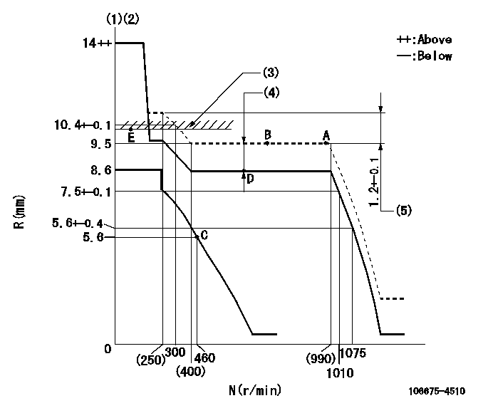
N:Pump speed
R:Rack position (mm)
(1)Target notch: K
(2)Tolerance for racks not indicated: +-0.05mm.
(3)RACK LIMIT
(4)Boost compensator stroke: BCL
(5)Rack difference between N = N1 and N = N2
----------
K=9 BCL=1.45+-0.1mm N1=975r/min N2=230r/min
----------
----------
K=9 BCL=1.45+-0.1mm N1=975r/min N2=230r/min
----------
Speed control lever angle
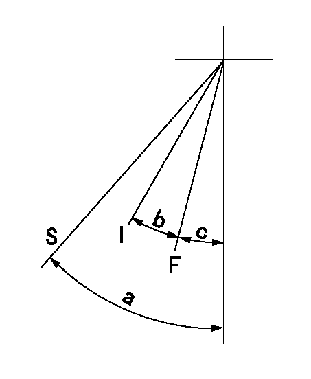
F:Full speed
I:Idle
S:Stop
----------
----------
a=35deg+-3deg b=19deg+-5deg c=2deg+-5deg
----------
----------
a=35deg+-3deg b=19deg+-5deg c=2deg+-5deg
Timing setting
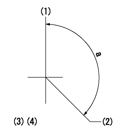
(1)Pump vertical direction
(2)Coupling's key groove position at No 1 cylinder's beginning of injection
(3)-
(4)-
----------
----------
a=(150deg)
----------
----------
a=(150deg)