
Rating:
Information injection-pump assembly
BOSCH
9 460 614 491
9460614491
ZEXEL
104742-4150
1047424150
NISSAN-DIESEL
167007T400
167007t400
Cross reference number
BOSCH
9 460 614 491
9460614491
ZEXEL
104742-4150
1047424150
NISSAN-DIESEL
167007T400
167007t400
Zexel num
Bosch num
Firm num
Name
104742-4150
9 460 614 491
167007T400 NISSAN-DIESEL
INJECTION-PUMP ASSEMBLY
K
K
Calibration Data:
Adjustment conditions
Test oil
1404 Test oil ISO4113orSAEJ967d
1404 Test oil ISO4113orSAEJ967d
Test oil temperature
degC
45
45
50
Nozzle
105780-0060
Bosch type code
NP-DN0SD1510
Nozzle holder
105780-2150
Opening pressure
MPa
13
13
13.3
Opening pressure
kgf/cm2
133
133
136
Injection pipe
157805-7320
Injection pipe
Inside diameter - outside diameter - length (mm) mm 2-6-450
Inside diameter - outside diameter - length (mm) mm 2-6-450
Joint assembly
157641-4720
Tube assembly
157641-4020
Transfer pump pressure
kPa
20
20
20
Transfer pump pressure
kgf/cm2
0.2
0.2
0.2
Direction of rotation (viewed from drive side)
Right R
Right R
Injection timing adjustment
Pump speed
r/min
1000
1000
1000
Average injection quantity
mm3/st.
61.4
60.9
61.9
Difference in delivery
mm3/st.
5
Basic
*
Oil temperature
degC
50
48
52
Injection timing adjustment_02
Pump speed
r/min
500
500
500
Average injection quantity
mm3/st.
40
36
44
Oil temperature
degC
48
46
50
Injection timing adjustment_03
Pump speed
r/min
760
760
760
Average injection quantity
mm3/st.
49
45.5
52.5
Oil temperature
degC
50
48
52
Injection timing adjustment_04
Pump speed
r/min
1000
1000
1000
Average injection quantity
mm3/st.
61.4
60.4
62.4
Difference in delivery
mm3/st.
5.5
Basic
*
Oil temperature
degC
50
48
52
Injection timing adjustment_05
Pump speed
r/min
1140
1140
1140
Average injection quantity
mm3/st.
62
58.5
65.5
Oil temperature
degC
50
48
52
Injection timing adjustment_06
Pump speed
r/min
1520
1520
1520
Average injection quantity
mm3/st.
74
70.5
77.5
Oil temperature
degC
50
48
52
Injection timing adjustment_07
Pump speed
r/min
1900
1900
1900
Average injection quantity
mm3/st.
73
68.5
77.5
Oil temperature
degC
50
48
52
Injection quantity adjustment
Pump speed
r/min
2150
2150
2150
Average injection quantity
mm3/st.
16.6
13.6
19.6
Difference in delivery
mm3/st.
5.5
Basic
*
Oil temperature
degC
52
50
54
Injection quantity adjustment_02
Pump speed
r/min
2300
2300
2300
Average injection quantity
mm3/st.
6
Oil temperature
degC
52
50
54
Injection quantity adjustment_03
Pump speed
r/min
2150
2150
2150
Average injection quantity
mm3/st.
16.6
13.1
20.1
Difference in delivery
mm3/st.
6
Basic
*
Oil temperature
degC
52
50
54
Governor adjustment
Pump speed
r/min
350
350
350
Average injection quantity
mm3/st.
5.8
3.8
7.8
Difference in delivery
mm3/st.
2
Basic
*
Oil temperature
degC
48
46
50
Timer adjustment
Pump speed
r/min
100
100
100
Average injection quantity
mm3/st.
70
50
90
Basic
*
Oil temperature
degC
48
46
50
Remarks
IDLE
IDLE
Timer adjustment_02
Pump speed
r/min
100
100
100
Average injection quantity
mm3/st.
70
50
90
Basic
*
Oil temperature
degC
48
46
50
Remarks
Full
Full
Timer adjustment_03
Pump speed
r/min
100
100
100
Average injection quantity
mm3/st.
70
50
90
Oil temperature
degC
48
46
50
Remarks
Full
Full
Speed control lever angle
Pump speed
r/min
350
350
350
Average injection quantity
mm3/st.
0
0
0
Oil temperature
degC
48
46
50
Remarks
Magnet OFF at idling position
Magnet OFF at idling position
Speed control lever angle_02
Pump speed
r/min
250
250
250
Average injection quantity
mm3/st.
5
Oil temperature
degC
48
46
50
Remarks
Magnet OFF at full-load position
Magnet OFF at full-load position
0000000901
Pump speed
r/min
1140
1140
1140
Overflow quantity with S/T ON
cm3/min
470
340
600
Oil temperature
degC
50
48
52
Remarks
With an O-ring
With an O-ring
_02
Pump speed
r/min
1140
1140
1140
Overflow quantity with S/T ON
cm3/min
470
340
600
Oil temperature
degC
50
48
52
Remarks
Without an O-ring
Without an O-ring
Stop lever angle
Pump speed
r/min
1140
1140
1140
Pressure with S/T OFF
kPa
343
314
372
Pressure with S/T OFF
kgf/cm2
3.5
3.2
3.8
Basic
*
Oil temperature
degC
50
48
52
Stop lever angle_02
Pump speed
r/min
1140
1140
1140
Pressure with S/T OFF
kPa
343
304
382
Pressure with S/T OFF
kgf/cm2
3.5
3.1
3.9
Basic
*
Oil temperature
degC
50
48
52
Stop lever angle_03
Pump speed
r/min
1520
1520
1520
Pressure with S/T OFF
kPa
412
334
471
Pressure with S/T OFF
kgf/cm2
4.2
3.4
4.8
Oil temperature
degC
50
48
52
0000001101
Pump speed
r/min
1520
1520
1520
Timer stroke with S/T OFF
mm
3.7
3.5
3.9
Basic
*
Oil temperature
degC
50
48
52
_02
Pump speed
r/min
1140
1140
1140
Timer stroke with S/T ON
mm
2.5
2.5
2.5
Timer stroke with S/T OFF
mm
1.3
0.9
1.9
Oil temperature
degC
50
48
52
_03
Pump speed
r/min
1520
1520
1520
Timer stroke with S/T OFF
mm
3.7
3.3
4.1
Basic
*
Oil temperature
degC
50
48
52
_04
Pump speed
r/min
2000
2000
2000
Timer stroke with S/T OFF
mm
8.2
7.7
8.6
Oil temperature
degC
50
48
52
0000001201
Max. applied voltage
V
8
8
8
Test voltage
V
13
12
14
Timing setting
K dimension
mm
3.1
3
3.2
KF dimension
mm
5.5
5.4
5.6
MS dimension
mm
0.7
0.6
0.8
Pre-stroke
mm
0.45
0.43
0.47
Control lever angle alpha
deg.
25
21
29
Control lever angle beta
deg.
36
31
41
Test data Ex:
0000001801 SUPPLY PUMP-TIMING DEVICE ADJ
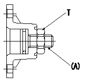
Pump chamber pressure PT, timer stroke TA adjustment procedure
Adjust the sequence in accordance with the procedure below.
1. At N = N1 set PT lower limit at P1.
2. At N = N2, set so that TA lower limit is TA1.
3. At N = N1 tap the regulating valve so that the timer's minimum specifications are obtained.
4. Reconfirm timer specifications for N = N2.
(1)If as specified, confirm timer operation at N = N3.
(2)If not as specified: 1) Readjust the timer at N = N2. (Adjust using the outer adjustable type). 2) Confirm timer operation at N = N1, N = N2.
T:Tightening torque
(A) = screw
----------
N1=1140r/min N2=1520r/min N3=2000r/min P1=314kPa(3.2kgf/cm2) TA1=3.5mm
----------
T=7~10N-m(0.7~1.0kgf-m)
----------
N1=1140r/min N2=1520r/min N3=2000r/min P1=314kPa(3.2kgf/cm2) TA1=3.5mm
----------
T=7~10N-m(0.7~1.0kgf-m)
0000001901 POTENTIOMETER ADJUSTMENT
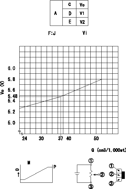
Adjustment of the potentiometer
In the following condition, change the installation position of the potentiometer to adjust the output voltage to within the specified values.
At pump speed N1 and with the control lever angle at a (corresponding to a shim thickness of L1), measure the injection quantity Q. Then, determine the voltage Vo from the voltage formula F and adjust the potentiometer.
J:Vo+-0.03
A = potentiometer performance specifications
C = control lever position
Q = injection quantity
Vo = output voltage
D = idle
E = full speed
Vi = applied voltage
M = potentiometer graph
O = output
P output at connecting harnesses 2 and 3
----------
N1=1140r/min a=13.4deg L1=8.65mm
----------
V1=(1.65+-0.4)V V2=(10.0)V J=Vo+-0.03=0.0245Q+4.5723
----------
N1=1140r/min a=13.4deg L1=8.65mm
----------
V1=(1.65+-0.4)V V2=(10.0)V J=Vo+-0.03=0.0245Q+4.5723
Have questions with 104742-4150?
Group cross 104742-4150 ZEXEL
Nissan-Diesel
104742-4150
9 460 614 491
167007T400
INJECTION-PUMP ASSEMBLY