Rating:
Information injection-pump assembly
ZEXEL
104741-4083
1047414083
NISSAN-DIESEL
1670054T09
1670054t09
Cross reference number
ZEXEL
104741-4083
1047414083
NISSAN-DIESEL
1670054T09
1670054t09
Zexel num
Bosch num
Firm num
Name
Calibration Data:
Adjustment conditions
Test oil
1404 Test oil ISO4113orSAEJ967d
1404 Test oil ISO4113orSAEJ967d
Test oil temperature
degC
45
45
50
Nozzle
105780-0060
Bosch type code
NP-DN0SD1510
Nozzle holder
105780-2150
Opening pressure
MPa
13
13
13.3
Opening pressure
kgf/cm2
133
133
136
Injection pipe
157805-7320
Injection pipe
Inside diameter - outside diameter - length (mm) mm 2-6-450
Inside diameter - outside diameter - length (mm) mm 2-6-450
Joint assembly
157641-4720
Tube assembly
157641-4020
Transfer pump pressure
kPa
20
20
20
Transfer pump pressure
kgf/cm2
0.2
0.2
0.2
Direction of rotation (viewed from drive side)
Right R
Right R
(Solenoid timer adjustment condition)
Limited to timer, pump chamber pressure. OFF
Limited to timer, pump chamber pressure. OFF
Injection timing adjustment
Pump speed
r/min
1000
1000
1000
Average injection quantity
mm3/st.
57.6
57.1
58.1
Difference in delivery
mm3/st.
4.5
Basic
*
Injection timing adjustment_02
Pump speed
r/min
2150
2150
2150
Average injection quantity
mm3/st.
18.3
14.8
21.8
Injection timing adjustment_03
Pump speed
r/min
2000
2000
2000
Average injection quantity
mm3/st.
62
56.5
67.5
Injection timing adjustment_04
Pump speed
r/min
1900
1900
1900
Average injection quantity
mm3/st.
64.1
59.6
68.6
Injection timing adjustment_05
Pump speed
r/min
1500
1500
1500
Average injection quantity
mm3/st.
63.3
59.8
66.8
Injection timing adjustment_06
Pump speed
r/min
1000
1000
1000
Average injection quantity
mm3/st.
57.6
56.6
58.6
Injection timing adjustment_07
Pump speed
r/min
750
750
750
Average injection quantity
mm3/st.
50.9
47.4
54.4
Injection timing adjustment_08
Pump speed
r/min
500
500
500
Average injection quantity
mm3/st.
45.6
41.6
49.6
Injection quantity adjustment
Pump speed
r/min
2150
2150
2150
Average injection quantity
mm3/st.
18.3
15.3
21.3
Difference in delivery
mm3/st.
5.5
Basic
*
Injection quantity adjustment_02
Pump speed
r/min
2300
2300
2300
Average injection quantity
mm3/st.
8
Governor adjustment
Pump speed
r/min
350
350
350
Average injection quantity
mm3/st.
9.9
7.9
11.9
Difference in delivery
mm3/st.
2
Basic
*
Governor adjustment_02
Pump speed
r/min
300
300
300
Average injection quantity
mm3/st.
14.6
9.6
19.6
Governor adjustment_03
Pump speed
r/min
350
350
350
Average injection quantity
mm3/st.
9.9
7.9
11.9
Governor adjustment_04
Pump speed
r/min
500
500
500
Average injection quantity
mm3/st.
5
Timer adjustment
Pump speed
r/min
100
100
100
Average injection quantity
mm3/st.
80
60
100
Basic
*
Speed control lever angle
Pump speed
r/min
350
350
350
Average injection quantity
mm3/st.
0
0
0
Remarks
Magnet OFF at idling position
Magnet OFF at idling position
Speed control lever angle_02
Pump speed
r/min
250
250
250
Average injection quantity
mm3/st.
5
Remarks
Magnet OFF at full-load position
Magnet OFF at full-load position
0000000901
Pump speed
r/min
1125
1125
1125
Overflow quantity with S/T ON
cm3/min
411
282
540
Stop lever angle
Pump speed
r/min
1125
1125
1125
Pressure with S/T OFF
kPa
264.5
235
294
Pressure with S/T OFF
kgf/cm2
2.7
2.4
3
Basic
*
Stop lever angle_02
Pump speed
r/min
1125
1125
1125
Pressure with S/T OFF
kPa
264.5
235
294
Pressure with S/T OFF
kgf/cm2
2.7
2.4
3
Stop lever angle_03
Pump speed
r/min
1500
1500
1500
Pressure with S/T OFF
kPa
343.5
275
412
Pressure with S/T OFF
kgf/cm2
3.5
2.8
4.2
Stop lever angle_04
Pump speed
r/min
1900
1900
1900
Pressure with S/T OFF
kPa
519.5
441
598
Pressure with S/T OFF
kgf/cm2
5.3
4.5
6.1
Stop lever angle_05
Pump speed
r/min
2150
2150
2150
Pressure with S/T OFF
kPa
785
Pressure with S/T OFF
kgf/cm2
8
0000001101
Pump speed
r/min
1125
1125
1125
Timer stroke with S/T OFF
mm
0.7
0.2
1.2
Basic
*
_02
Pump speed
r/min
1500
1500
1500
Timer stroke with S/T OFF
mm
2.8
2.6
3
Basic
*
_03
Pump speed
r/min
1125
1125
1125
Timer stroke with S/T OFF
mm
0.7
0.1
1.3
_04
Pump speed
r/min
1500
1500
1500
Timer stroke with S/T OFF
mm
2.8
2.5
3.1
_05
Pump speed
r/min
1900
1900
1900
Timer stroke with S/T OFF
mm
6.1
5.6
6.6
0000001201
Max. applied voltage
V
16
16
16
Test voltage
V
25
24
26
Timing setting
K dimension
mm
3.1
3
3.2
KF dimension
mm
5.5
5.4
5.6
MS dimension
mm
0.7
0.6
0.8
Pre-stroke
mm
0.45
0.43
0.47
Control lever angle alpha
deg.
25
21
29
Control lever angle beta
deg.
36
31
41
Test data Ex:
0000001801 SUPPLY PUMP-TIMING DEVICE ADJ

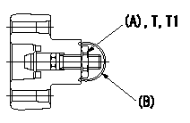
Pump chamber pressure PT, timer stroke TA adjustment procedure
Adjust the sequence in accordance with the procedure below.
1. At N = N1 set PT lower limit at P1.
2. At N = N2, set so that TA lower limit is TA1.
3. At N = N1 tap the regulating valve so that the timer's minimum specifications are obtained.
4. Reconfirm timer specifications for N = N2.
(1)If as specified, confirm timer operation at N = N3.
(2)If not as specified: 1) Readjust the timer at N = N2. (Adjust using the outer adjustable type). 2) Confirm timer operation at N = N1, N = N2.
5. Seal after completing adjustment.
T:Tightening torque
(A) = nut
(B) = sealing wire
----------
N1=1125r/min N2=1500r/min N3=1900r/min P1=235kPa(2.4kgf/cm2) TA1=2.6mm T,T1=12~15N-m(1.2~1.5kg-m)
----------
----------
N1=1125r/min N2=1500r/min N3=1900r/min P1=235kPa(2.4kgf/cm2) TA1=2.6mm T,T1=12~15N-m(1.2~1.5kg-m)
----------
0000001901 ACCELERATOR SWITCH ADJ

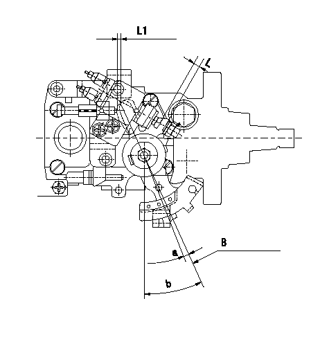
Adjustment of the accelerator switch
ON - OFF changeover point: from idle to c (shim thickness L1 mm)
Idle-c: ON
d ~ full: OFF
B = idle lever position
Adjust only amount that screw protrudes L1. Shim adjustment not necessary.
----------
L1=1.4+-0.13mm c=2.1deg d=2.1deg e=2.1+-2deg L=6.5+-0.4mm
----------
L1=(1.4mm) a=(2.1+-2deg) b=25+-4deg L=6.5+-0.4mm
----------
L1=1.4+-0.13mm c=2.1deg d=2.1deg e=2.1+-2deg L=6.5+-0.4mm
----------
L1=(1.4mm) a=(2.1+-2deg) b=25+-4deg L=6.5+-0.4mm