Rating:
Information injection-pump assembly
BOSCH
9 400 614 773
9400614773
ZEXEL
101602-2431
1016022431
HINO
220006111A
220006111a
Service parts 101602-2431 INJECTION-PUMP ASSEMBLY:
1.
_
5.
AUTOM. ADVANCE MECHANIS
6.
COUPLING PLATE
8.
_
9.
_
11.
Nozzle and Holder
23600-2080A
12.
Open Pre:MPa(Kqf/cm2)
17.7{180}
15.
NOZZLE SET
Cross reference number
BOSCH
9 400 614 773
9400614773
ZEXEL
101602-2431
1016022431
HINO
220006111A
220006111a
Zexel num
Bosch num
Firm num
Name
101602-2431
9 400 614 773
220006111A HINO
INJECTION-PUMP ASSEMBLY
W06E * K
W06E * K
Calibration Data:
Adjustment conditions
Test oil
1404 Test oil ISO4113 or {SAEJ967d}
1404 Test oil ISO4113 or {SAEJ967d}
Test oil temperature
degC
40
40
45
Nozzle and nozzle holder
105780-8140
Bosch type code
EF8511/9A
Nozzle
105780-0000
Bosch type code
DN12SD12T
Nozzle holder
105780-2080
Bosch type code
EF8511/9
Opening pressure
MPa
17.2
Opening pressure
kgf/cm2
175
Injection pipe
Outer diameter - inner diameter - length (mm) mm 6-2-600
Outer diameter - inner diameter - length (mm) mm 6-2-600
Overflow valve
131424-5720
Overflow valve opening pressure
kPa
255
221
289
Overflow valve opening pressure
kgf/cm2
2.6
2.25
2.95
Tester oil delivery pressure
kPa
157
157
157
Tester oil delivery pressure
kgf/cm2
1.6
1.6
1.6
Direction of rotation (viewed from drive side)
Right R
Right R
Injection timing adjustment
Direction of rotation (viewed from drive side)
Right R
Right R
Injection order
1-4-2-6-
3-5
Pre-stroke
mm
3.1
3.07
3.13
Beginning of injection position
Drive side NO.1
Drive side NO.1
Difference between angles 1
Cal 1-4 deg. 60 59.75 60.25
Cal 1-4 deg. 60 59.75 60.25
Difference between angles 2
Cyl.1-2 deg. 120 119.75 120.25
Cyl.1-2 deg. 120 119.75 120.25
Difference between angles 3
Cal 1-6 deg. 180 179.75 180.25
Cal 1-6 deg. 180 179.75 180.25
Difference between angles 4
Cal 1-3 deg. 240 239.75 240.25
Cal 1-3 deg. 240 239.75 240.25
Difference between angles 5
Cal 1-5 deg. 300 299.75 300.25
Cal 1-5 deg. 300 299.75 300.25
Injection quantity adjustment
Adjusting point
-
Rack position
9.4
Pump speed
r/min
800
800
800
Average injection quantity
mm3/st.
45.9
43.9
47.9
Max. variation between cylinders
%
0
-3.5
3.5
Basic
*
Fixing the rack
*
Standard for adjustment of the maximum variation between cylinders
*
Injection quantity adjustment_02
Adjusting point
H
Rack position
8.5+-0.5
Pump speed
r/min
250
250
250
Average injection quantity
mm3/st.
9
7.5
10.5
Max. variation between cylinders
%
0
-10
10
Fixing the rack
*
Standard for adjustment of the maximum variation between cylinders
*
Remarks
Adjust only variation between cylinders; adjust governor according to governor specifications.
Adjust only variation between cylinders; adjust governor according to governor specifications.
Injection quantity adjustment_03
Adjusting point
A
Rack position
R1(9.4)
Pump speed
r/min
800
800
800
Average injection quantity
mm3/st.
45.9
44.9
46.9
Basic
*
Fixing the lever
*
Injection quantity adjustment_04
Adjusting point
B
Rack position
R1+0.2
Pump speed
r/min
1200
1200
1200
Average injection quantity
mm3/st.
59.7
55.7
63.7
Fixing the lever
*
Injection quantity adjustment_05
Adjusting point
C
Rack position
R1-0.4
Pump speed
r/min
500
500
500
Average injection quantity
mm3/st.
26.1
22.1
30.1
Fixing the lever
*
Injection quantity adjustment_06
Adjusting point
I
Rack position
-
Pump speed
r/min
100
100
100
Average injection quantity
mm3/st.
92
92
102
Fixing the lever
*
Rack limit
*
Test data Ex:
Governor adjustment
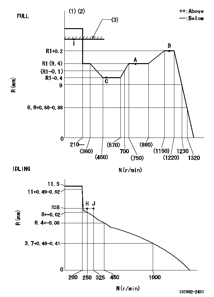
N:Pump speed
R:Rack position (mm)
(1)Torque cam stamping: T1
(2)Tolerance for racks not indicated: +-0.05mm.
(3)RACK LIMIT
----------
T1=E30
----------
----------
T1=E30
----------
Speed control lever angle
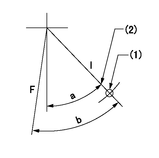
F:Full speed
I:Idle
(1)Use the hole at R = aa
(2)Stopper bolt set position 'H'
----------
aa=55mm
----------
a=34deg+-5deg b=(35deg)+-3deg
----------
aa=55mm
----------
a=34deg+-5deg b=(35deg)+-3deg
Stop lever angle
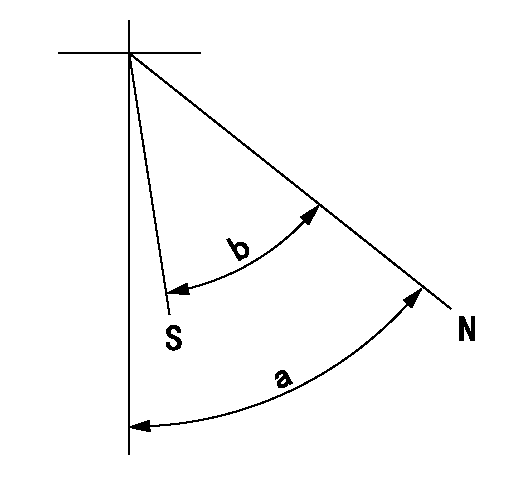
N:Pump normal
S:Stop the pump.
----------
----------
a=40deg+-5deg b=40deg+-5deg
----------
----------
a=40deg+-5deg b=40deg+-5deg
Timing setting

(1)Pump vertical direction
(2)Position of gear's standard threaded hole at No 1 cylinder's beginning of injection
(3)-
(4)-
----------
----------
a=(70deg)
----------
----------
a=(70deg)
Have questions with 101602-2431?
Group cross 101602-2431 ZEXEL
Hino
Hino
101602-2431
9 400 614 773
220006111A
INJECTION-PUMP ASSEMBLY
W06E
W06E