Rating:
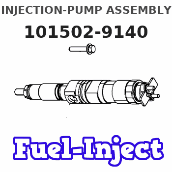
Information injection-pump assembly
BOSCH
F 019 Z10 972
f019z10972
ZEXEL
101502-9140
1015029140
KUBOTA
1G41751011
1g41751011
Service parts 101502-9140 INJECTION-PUMP ASSEMBLY:
1.
_
6.
COUPLING PLATE
7.
COUPLING PLATE
8.
_
9.
_
11.
Nozzle and Holder
12.
Open Pre:MPa(Kqf/cm2)
18.6(190)/22.6(230)
14.
NOZZLE
Cross reference number
BOSCH
F 019 Z10 972
f019z10972
ZEXEL
101502-9140
1015029140
KUBOTA
1G41751011
1g41751011
Zexel num
Bosch num
Firm num
Name
101502-9140
F 019 Z10 972
1G41751011 KUBOTA
INJECTION-PUMP ASSEMBLY
F5802- K 14BZ INJECTION PUMP ASSY PE
F5802- K 14BZ INJECTION PUMP ASSY PE
Calibration Data:
Adjustment conditions
Test oil
1404 Test oil ISO4113 or {SAEJ967d}
1404 Test oil ISO4113 or {SAEJ967d}
Test oil temperature
degC
40
40
45
Nozzle and nozzle holder
105780-8140
Bosch type code
EF8511/9A
Nozzle
105780-0000
Bosch type code
DN12SD12T
Nozzle holder
105780-2080
Bosch type code
EF8511/9
Opening pressure
MPa
17.2
Opening pressure
kgf/cm2
175
Injection pipe
Outer diameter - inner diameter - length (mm) mm 6-2-600
Outer diameter - inner diameter - length (mm) mm 6-2-600
Overflow valve
134424-4120
Overflow valve opening pressure
kPa
255
221
289
Overflow valve opening pressure
kgf/cm2
2.6
2.25
2.95
Tester oil delivery pressure
kPa
255
255
255
Tester oil delivery pressure
kgf/cm2
2.6
2.6
2.6
Direction of rotation (viewed from drive side)
Left L
Left L
Injection timing adjustment
Direction of rotation (viewed from drive side)
Left L
Left L
Injection order
1-3-5-4-
2
Pre-stroke
mm
4
3.95
4.05
Rack position
Point A R=A
Point A R=A
Beginning of injection position
Drive side NO.1
Drive side NO.1
Difference between angles 1
Cal 1-3 deg. 72 71.5 72.5
Cal 1-3 deg. 72 71.5 72.5
Difference between angles 2
Cal 1-5 deg. 144 143.5 144.5
Cal 1-5 deg. 144 143.5 144.5
Difference between angles 3
Cal 1-4 deg. 216 215.5 216.5
Cal 1-4 deg. 216 215.5 216.5
Difference between angles 4
Cyl.1-2 deg. 288 287.5 288.5
Cyl.1-2 deg. 288 287.5 288.5
Injection quantity adjustment
Adjusting point
A
Rack position
10.9
Pump speed
r/min
1200
1200
1200
Average injection quantity
mm3/st.
91.5
90.5
92.5
Max. variation between cylinders
%
0
-2.5
2.5
Basic
*
Fixing the lever
*
Injection quantity adjustment_02
Adjusting point
B
Rack position
10.25
Pump speed
r/min
650
650
650
Average injection quantity
mm3/st.
94
84
104
Fixing the lever
*
Injection quantity adjustment_03
Adjusting point
C
Rack position
6.1+-0.5
Pump speed
r/min
350
350
350
Average injection quantity
mm3/st.
12
10
14
Max. variation between cylinders
%
0
-15
15
Fixing the rack
*
Timer adjustment
Pump speed
r/min
(800)
Advance angle
deg.
0.5
Timer adjustment_02
Pump speed
r/min
(1100)
Advance angle
deg.
2
1.7
2.3
Remarks
Finish
Finish
Test data Ex:
Governor adjustment
N:Pump speed
R:Rack position (mm)
(1)Target notch: K
(2)Tolerance for racks not indicated: +-0.05mm.
(3)Rack difference between N = N1 and N = N2
(4)Rack difference between N = N3 and N = N4
(5)Idle sub spring setting: L1.
----------
K=10 N1=1200r/min N2=650r/min N3=1200r/min N4=350r/min L1=6.7-0.5mm
----------
----------
K=10 N1=1200r/min N2=650r/min N3=1200r/min N4=350r/min L1=6.7-0.5mm
----------
Speed control lever angle
F:Full speed
I:Idle
(1)Stopper bolt setting
----------
----------
a=17deg+-5deg b=37deg+-5deg
----------
----------
a=17deg+-5deg b=37deg+-5deg
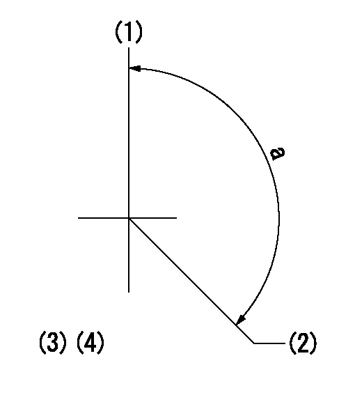
Stop lever angle
N:Pump normal
S:Stop the pump.
(1)Normal
(2)Use the hole at R = aa
----------
aa=60mm
----------
a=19deg+-5deg b=53deg+-5deg
----------
aa=60mm
----------
a=19deg+-5deg b=53deg+-5deg
Timing setting
(1)Pump vertical direction
(2)Position of camshaft's key groove at No 1 cylinder's beginning of injection
(3)At rack position = aa
(4)-
----------
aa=10.9mm
----------
a=(130deg)
----------
aa=10.9mm
----------
a=(130deg)
Have questions with 101502-9140?
Group cross 101502-9140 ZEXEL
Kubota
101502-9140
F 019 Z10 972
1G41751011
INJECTION-PUMP ASSEMBLY
F5802-
F5802-