
Rating:
Information injection-pump assembly
BOSCH
F 019 Z10 277
f019z10277
ZEXEL
106873-2942
1068732942
Service parts 106873-2942 INJECTION-PUMP ASSEMBLY:
1.
_
7.
COUPLING PLATE
8.
_
9.
_
11.
Nozzle and Holder
ME093732
12.
Open Pre:MPa(Kqf/cm2)
17.7{180}/21.6{220}
14.
NOZZLE
Include in #1:
106873-2942
as INJECTION-PUMP ASSEMBLY
Cross reference number
BOSCH
F 019 Z10 277
f019z10277
ZEXEL
106873-2942
1068732942
Zexel num
Bosch num
Firm num
Name
Calibration Data:
Adjustment conditions
Test oil
1404 Test oil ISO4113 or {SAEJ967d}
1404 Test oil ISO4113 or {SAEJ967d}
Test oil temperature
degC
40
40
45
Nozzle and nozzle holder
105780-8140
Bosch type code
EF8511/9A
Nozzle
105780-0000
Bosch type code
DN12SD12T
Nozzle holder
105780-2080
Bosch type code
EF8511/9
Opening pressure
MPa
17.2
Opening pressure
kgf/cm2
175
Injection pipe
Outer diameter - inner diameter - length (mm) mm 8-3-600
Outer diameter - inner diameter - length (mm) mm 8-3-600
Overflow valve
131425-0220
Overflow valve opening pressure
kPa
157
123
191
Overflow valve opening pressure
kgf/cm2
1.6
1.25
1.95
Tester oil delivery pressure
kPa
157
157
157
Tester oil delivery pressure
kgf/cm2
1.6
1.6
1.6
Direction of rotation (viewed from drive side)
Right R
Right R
Injection timing adjustment
Direction of rotation (viewed from drive side)
Right R
Right R
Injection order
1-2-7-3-
4-5-6-8
Pre-stroke
mm
3.9
3.85
3.95
Beginning of injection position
Governor side NO.1
Governor side NO.1
Difference between angles 1
Cyl.1-2 deg. 45 44.5 45.5
Cyl.1-2 deg. 45 44.5 45.5
Difference between angles 2
Cal 1-7 deg. 90 89.5 90.5
Cal 1-7 deg. 90 89.5 90.5
Difference between angles 3
Cal 1-3 deg. 135 134.5 135.5
Cal 1-3 deg. 135 134.5 135.5
Difference between angles 4
Cal 1-4 deg. 180 179.5 180.5
Cal 1-4 deg. 180 179.5 180.5
Difference between angles 5
Cal 1-5 deg. 225 224.5 225.5
Cal 1-5 deg. 225 224.5 225.5
Difference between angles 6
Cal 1-6 deg. 270 269.5 270.5
Cal 1-6 deg. 270 269.5 270.5
Difference between angles 7
Cal 1-8 deg. 315 314.5 315.5
Cal 1-8 deg. 315 314.5 315.5
Injection quantity adjustment
Adjusting point
-
Rack position
12.2
Pump speed
r/min
700
700
700
Each cylinder's injection qty
mm3/st.
109
105.7
112.3
Basic
*
Fixing the rack
*
Standard for adjustment of the maximum variation between cylinders
*
Injection quantity adjustment_02
Adjusting point
Z
Rack position
8.5+-0.5
Pump speed
r/min
510
510
510
Each cylinder's injection qty
mm3/st.
16
13.6
18.4
Fixing the rack
*
Standard for adjustment of the maximum variation between cylinders
*
Injection quantity adjustment_03
Adjusting point
A
Rack position
R1(12.2)
Pump speed
r/min
700
700
700
Average injection quantity
mm3/st.
109
108
110
Basic
*
Fixing the lever
*
Injection quantity adjustment_04
Adjusting point
B
Rack position
R1+1.15
Pump speed
r/min
1100
1100
1100
Average injection quantity
mm3/st.
118
114
122
Fixing the lever
*
Injection quantity adjustment_05
Adjusting point
C
Rack position
(R1-0.8)
Pump speed
r/min
500
500
500
Average injection quantity
mm3/st.
104
100
108
Fixing the lever
*
Test data Ex:
Governor adjustment
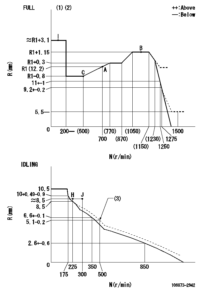
N:Pump speed
R:Rack position (mm)
(1)Torque cam stamping: T1
(2)Tolerance for racks not indicated: +-0.05mm.
(3)Damper spring setting
----------
T1=AB22
----------
----------
T1=AB22
----------
Timer adjustment
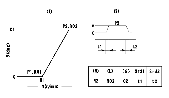
(1)Adjusting range
(2)Step response time
(N): Speed of the pump
(L): Load
(theta) Advance angle
(Srd1) Step response time 1
(Srd2) Step response time 2
1. Adjusting conditions for the variable timer
(1)Adjust the clearance between the pickup and the protrusion to L.
----------
L=1-0.2mm N2=800r/min C2=(10)deg t1=2.5--sec. t2=2.5--sec.
----------
N1=750++r/min P1=0kPa(0kgf/cm2) P2=392kPa(4kgf/cm2) C1=10+-0.3deg R01=0/4load R02=4/4load
----------
L=1-0.2mm N2=800r/min C2=(10)deg t1=2.5--sec. t2=2.5--sec.
----------
N1=750++r/min P1=0kPa(0kgf/cm2) P2=392kPa(4kgf/cm2) C1=10+-0.3deg R01=0/4load R02=4/4load
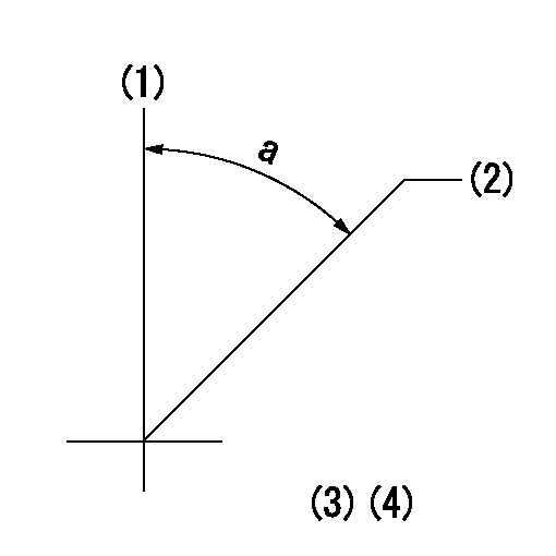
Speed control lever angle
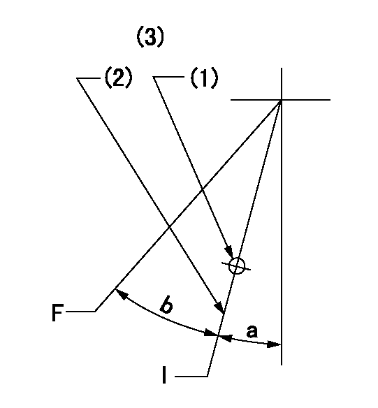
F:Full speed
I:Idle
(1)Use the hole at R = aa
(2)Stopper bolt set position 'H'
(3)Viewed from feed pump side.
----------
aa=37.5mm
----------
a=30deg+-5deg b=(44deg)+-3deg
----------
aa=37.5mm
----------
a=30deg+-5deg b=(44deg)+-3deg
Stop lever angle
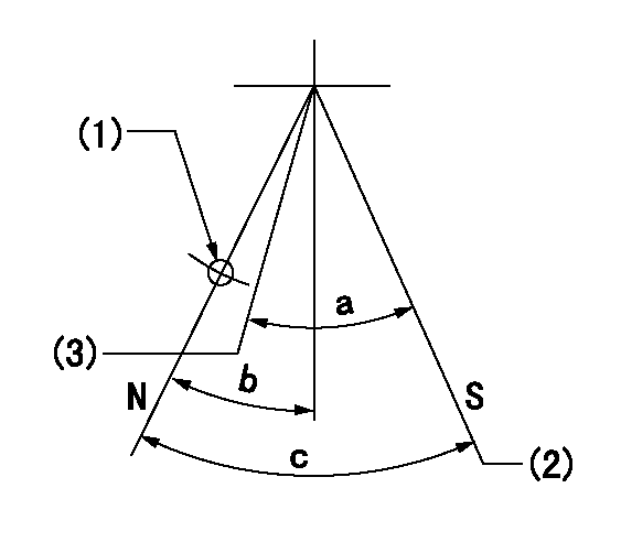
N:Pump normal
S:Stop the pump.
(1)Use the hole at R = aa
(2)Set the stopper bolt so that speed = bb and rack position = cc. (Confirm non-injection.)
(3)Normal engine position (Rack position corresponding to dd)
----------
aa=31.5mm bb=1100r/min cc=3.5+-0.3mm dd=18mm
----------
a=(31deg)+-5deg b=11.5deg+-5deg c=41deg+-5deg
----------
aa=31.5mm bb=1100r/min cc=3.5+-0.3mm dd=18mm
----------
a=(31deg)+-5deg b=11.5deg+-5deg c=41deg+-5deg
0000001501 MICRO SWITCH
Adjustment of the micro-switch
Adjust the bolt to obtain the following lever position when the micro-switch is ON.
(1)Speed N1
(2)Rack position Ra
----------
N1=325r/min Ra=8.5+-0.1mm
----------
----------
N1=325r/min Ra=8.5+-0.1mm
----------
0000001601 RACK SENSOR

(VR) measurement voltage
(I) Part number of the control unit
(G) Apply red paint.
(H): End surface of the pump
1. Rack sensor adjustment (-0620)
(1)Fix the speed control lever at the full position
(2)Set the speed to N1 r/min.
(If the boost compensator is provided, apply boost pressure.)
(3)Adjust the bobbin (A) so that the rack sensor's output voltage is VR+-0.01.
(4)At that time, rack position must be Ra.
(5)Apply G at two places.
Connecting part between the joint (B) and the nut (F)
Connecting part between the joint (B) and the end surface of the pump (H)
----------
N1=1100r/min Ra=R1(12.2)+1.15mm
----------
----------
N1=1100r/min Ra=R1(12.2)+1.15mm
----------
Timing setting
(1)Pump vertical direction
(2)Coupling's key groove position at No 1 cylinder's beginning of injection
(3)B.T.D.C.: aa
(4)-
----------
aa=4deg
----------
a=(50deg)
----------
aa=4deg
----------
a=(50deg)