
Rating:
Information injection-pump assembly
ZEXEL
106693-6162
1066936162
ISUZU
8943949462
8943949462
Service parts 106693-6162 INJECTION-PUMP ASSEMBLY:
1.
_
7.
COUPLING PLATE
8.
_
9.
_
11.
Nozzle and Holder
8-94394-213-0
12.
Open Pre:MPa(Kqf/cm2)
18.1{185}/22.1{225}
15.
NOZZLE SET
Include in #1:
106693-6162
as INJECTION-PUMP ASSEMBLY
Cross reference number
ZEXEL
106693-6162
1066936162
ISUZU
8943949462
8943949462
Zexel num
Bosch num
Firm num
Name
Calibration Data:
Adjustment conditions
Test oil
1404 Test oil ISO4113 or {SAEJ967d}
1404 Test oil ISO4113 or {SAEJ967d}
Test oil temperature
degC
40
40
45
Nozzle and nozzle holder
105780-8250
Bosch type code
1 688 901 101
Nozzle
105780-0120
Bosch type code
1 688 901 990
Nozzle holder
105780-2190
Opening pressure
MPa
20.7
Opening pressure
kgf/cm2
211
Injection pipe
Outer diameter - inner diameter - length (mm) mm 8-3-600
Outer diameter - inner diameter - length (mm) mm 8-3-600
Overflow valve
131424-8620
Overflow valve opening pressure
kPa
206
172
240
Overflow valve opening pressure
kgf/cm2
2.1
1.75
2.45
Tester oil delivery pressure
kPa
255
255
255
Tester oil delivery pressure
kgf/cm2
2.6
2.6
2.6
Direction of rotation (viewed from drive side)
Left L
Left L
Injection timing adjustment
Direction of rotation (viewed from drive side)
Left L
Left L
Injection order
1-5-3-6-
2-4
Pre-stroke
mm
3.6
3.57
3.63
Rack position
Point A R=A
Point A R=A
Beginning of injection position
Governor side NO.1
Governor side NO.1
Difference between angles 1
Cal 1-5 deg. 60 59.75 60.25
Cal 1-5 deg. 60 59.75 60.25
Difference between angles 2
Cal 1-3 deg. 120 119.75 120.25
Cal 1-3 deg. 120 119.75 120.25
Difference between angles 3
Cal 1-6 deg. 180 179.75 180.25
Cal 1-6 deg. 180 179.75 180.25
Difference between angles 4
Cyl.1-2 deg. 240 239.75 240.25
Cyl.1-2 deg. 240 239.75 240.25
Difference between angles 5
Cal 1-4 deg. 300 299.75 300.25
Cal 1-4 deg. 300 299.75 300.25
Injection quantity adjustment
Adjusting point
-
Rack position
11.4
Pump speed
r/min
700
700
700
Average injection quantity
mm3/st.
108
106
110
Max. variation between cylinders
%
0
-3
3
Basic
*
Fixing the rack
*
Standard for adjustment of the maximum variation between cylinders
*
Injection quantity adjustment_02
Adjusting point
Z
Rack position
8+-0.5
Pump speed
r/min
425
425
425
Average injection quantity
mm3/st.
12.5
9.3
15.7
Max. variation between cylinders
%
0
-13
13
Fixing the rack
*
Standard for adjustment of the maximum variation between cylinders
*
Injection quantity adjustment_03
Adjusting point
A
Rack position
R1(11.4)
Pump speed
r/min
700
700
700
Average injection quantity
mm3/st.
108
107
109
Basic
*
Fixing the lever
*
Boost pressure
kPa
72
72
Boost pressure
mmHg
540
540
Injection quantity adjustment_04
Adjusting point
B
Rack position
R1+0.9
Pump speed
r/min
1200
1200
1200
Average injection quantity
mm3/st.
108
104
112
Fixing the lever
*
Boost pressure
kPa
72
72
Boost pressure
mmHg
540
540
Boost compensator adjustment
Pump speed
r/min
525
525
525
Rack position
R2-1.7
Boost pressure
kPa
12
10.7
13.3
Boost pressure
mmHg
90
80
100
Boost compensator adjustment_02
Pump speed
r/min
525
525
525
Rack position
R1-0.2(R
2)
Boost pressure
kPa
58.7
58.7
58.7
Boost pressure
mmHg
440
440
440
Timer adjustment
Pump speed
r/min
900--
Advance angle
deg.
0
0
0
Load
3/5
Remarks
Start
Start
Timer adjustment_02
Pump speed
r/min
850
Advance angle
deg.
0.3
Load
3/5
Timer adjustment_03
Pump speed
r/min
-
Advance angle
deg.
1.5
1
2
Load
3/5
Remarks
Measure the actual speed.
Measure the actual speed.
Timer adjustment_04
Pump speed
r/min
1075
Advance angle
deg.
1.5
1
2
Load
4/5
Timer adjustment_05
Pump speed
r/min
1350
Advance angle
deg.
5.5
5
6
Load
4/5
Remarks
Finish
Finish
Test data Ex:
Governor adjustment
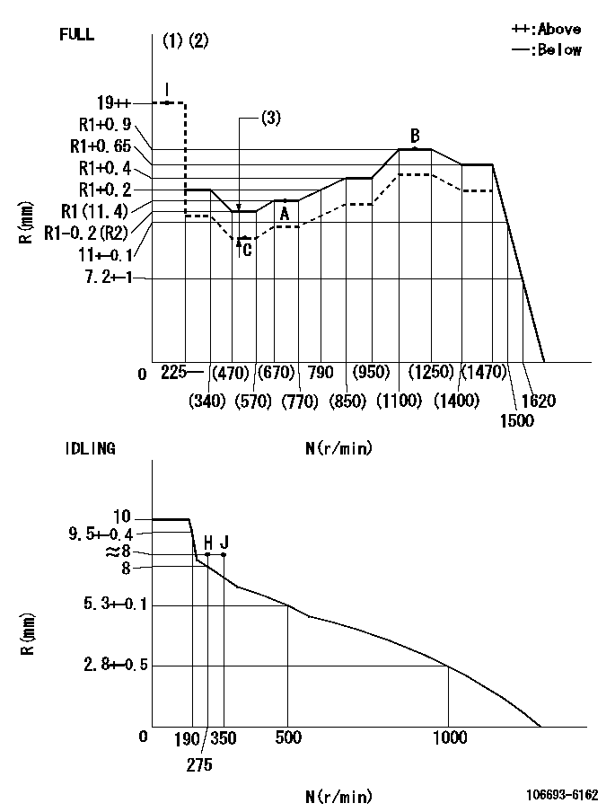
N:Pump speed
R:Rack position (mm)
(1)Torque cam stamping: T1
(2)Tolerance for racks not indicated: +-0.05mm.
(3)Boost compensator stroke: BCL
----------
T1=AC30 BCL=1.7+-0.1mm
----------
----------
T1=AC30 BCL=1.7+-0.1mm
----------
Speed control lever angle
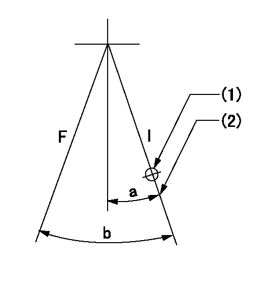
F:Full speed
I:Idle
(1)Use the pin at R = aa
(2)Stopper bolt set position 'H'
----------
aa=35mm
----------
a=20deg+-5deg b=38deg+-3deg
----------
aa=35mm
----------
a=20deg+-5deg b=38deg+-3deg
Stop lever angle
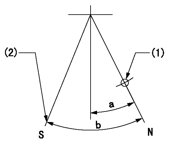
N:Pump normal
S:Stop the pump.
(1)Use the pin at R = aa
(2)Set the stopper bolt at rack position = bb, speed = cc and confirm non-injection.
----------
aa=40mm bb=1.5+-0.3mm cc=0r/min
----------
a=12deg+-5deg b=44deg+-5deg
----------
aa=40mm bb=1.5+-0.3mm cc=0r/min
----------
a=12deg+-5deg b=44deg+-5deg
Timing setting

(1)Pump vertical direction
(2)Position of timer's threaded hole at No 1 cylinder's beginning of injection
(3)B.T.D.C.: aa
(4)-
----------
aa=7deg
----------
a=(50deg)
----------
aa=7deg
----------
a=(50deg)