Rating:
Information injection-pump assembly
BOSCH
F 01G 09W 00H
f01g09w00h
ZEXEL
104746-5151
1047465151
ISUZU
8972888381
8972888381
Cross reference number
BOSCH
F 01G 09W 00H
f01g09w00h
ZEXEL
104746-5151
1047465151
ISUZU
8972888381
8972888381
Zexel num
Bosch num
Firm num
Name
104746-5151
F 01G 09W 00H
8972888381 ISUZU
INJECTION-PUMP ASSEMBLY
4JA1 * K
4JA1 * K
Calibration Data:
Adjustment conditions
Test oil
1404 Test oil ISO4113orSAEJ967d
1404 Test oil ISO4113orSAEJ967d
Test oil temperature
degC
45
45
50
Nozzle
105780-0060
Bosch type code
NP-DN0SD1510
Nozzle holder
105780-2150
Opening pressure
MPa
13
13
13.3
Opening pressure
kgf/cm2
133
133
136
Injection pipe
157805-7320
Injection pipe
Inside diameter - outside diameter - length (mm) mm 2-6-450
Inside diameter - outside diameter - length (mm) mm 2-6-450
Joint assembly
157641-4720
Tube assembly
157641-4020
Transfer pump pressure
kPa
20
20
20
Transfer pump pressure
kgf/cm2
0.2
0.2
0.2
Direction of rotation (viewed from drive side)
Right R
Right R
Injection timing adjustment
Pump speed
r/min
1150
1150
1150
Average injection quantity
mm3/st.
58.8
58.3
59.3
Difference in delivery
mm3/st.
5
Basic
*
Oil temperature
degC
50
48
52
Injection timing adjustment_02
Pump speed
r/min
500
500
500
Average injection quantity
mm3/st.
28
24.5
33.5
Oil temperature
degC
48
46
50
Injection timing adjustment_03
Pump speed
r/min
750
750
750
Average injection quantity
mm3/st.
37.5
34
41
Oil temperature
degC
50
48
52
Injection timing adjustment_04
Pump speed
r/min
1150
1150
1150
Average injection quantity
mm3/st.
58.8
57.8
59.8
Difference in delivery
mm3/st.
5
Basic
*
Oil temperature
degC
50
48
52
Injection timing adjustment_05
Pump speed
r/min
1900
1900
1900
Average injection quantity
mm3/st.
68.7
64.7
72.7
Oil temperature
degC
50
48
52
Injection quantity adjustment
Pump speed
r/min
2350
2350
2350
Average injection quantity
mm3/st.
26.6
23.6
29.6
Difference in delivery
mm3/st.
4
Basic
*
Oil temperature
degC
52
50
54
Injection quantity adjustment_02
Pump speed
r/min
2700
2700
2700
Average injection quantity
mm3/st.
5
Oil temperature
degC
55
52
58
Injection quantity adjustment_03
Pump speed
r/min
2350
2350
2350
Average injection quantity
mm3/st.
26.6
23.6
29.6
Difference in delivery
mm3/st.
4
Basic
*
Oil temperature
degC
52
50
54
Governor adjustment
Pump speed
r/min
385
385
385
Average injection quantity
mm3/st.
8.2
6.2
10.2
Difference in delivery
mm3/st.
2
Basic
*
Oil temperature
degC
48
46
50
Governor adjustment_02
Pump speed
r/min
385
385
385
Average injection quantity
mm3/st.
8.2
6.2
10.2
Difference in delivery
mm3/st.
2
Basic
*
Oil temperature
degC
48
46
50
Timer adjustment
Pump speed
r/min
100
100
100
Average injection quantity
mm3/st.
60
60
100
Basic
*
Oil temperature
degC
48
46
50
Remarks
Full
Full
Timer adjustment_02
Pump speed
r/min
100
100
100
Average injection quantity
mm3/st.
60
60
100
Oil temperature
degC
48
46
50
Remarks
Full
Full
Speed control lever angle
Pump speed
r/min
385
385
385
Average injection quantity
mm3/st.
0
0
0
Oil temperature
degC
48
46
50
Remarks
Magnet OFF at idling position
Magnet OFF at idling position
0000000901
Pump speed
r/min
1500
1500
1500
Overflow quantity
cm3/min
380
250
510
Oil temperature
degC
50
48
52
Stop lever angle
Pump speed
r/min
1500
1500
1500
Pressure
kPa
412
392
432
Pressure
kgf/cm2
4.2
4
4.4
Basic
*
Oil temperature
degC
50
48
52
Stop lever angle_02
Pump speed
r/min
1500
1500
1500
Pressure
kPa
412
392
432
Pressure
kgf/cm2
4.2
4
4.4
Basic
*
Oil temperature
degC
50
48
52
0000001101
Pump speed
r/min
1500
1500
1500
Timer stroke
mm
2.4
2.2
2.6
Basic
*
Oil temperature
degC
50
48
52
_02
Pump speed
r/min
1000
1000
1000
Timer stroke
mm
0.5
Oil temperature
degC
50
48
52
_03
Pump speed
r/min
1500
1500
1500
Timer stroke
mm
2.4
2.2
2.6
Basic
*
Oil temperature
degC
50
48
52
_04
Pump speed
r/min
1700
1700
1700
Timer stroke
mm
3.4
3
3.8
Oil temperature
degC
50
48
52
_05
Pump speed
r/min
2050
2050
2050
Timer stroke
mm
5.3
5
5.7
Oil temperature
degC
52
50
54
0000001201
Max. applied voltage
V
8
8
8
Test voltage
V
13
12
14
Timing setting
K dimension
mm
3.1
3
3.2
KF dimension
mm
5.5
5.4
5.6
MS dimension
mm
0.8
0.7
0.9
Pre-stroke
mm
0.45
0.43
0.47
Control lever angle alpha
deg.
18
14
22
Control lever angle beta
deg.
35
30
40
Test data Ex:
0000001801 POTENTIOMETER ADJUSTMENT
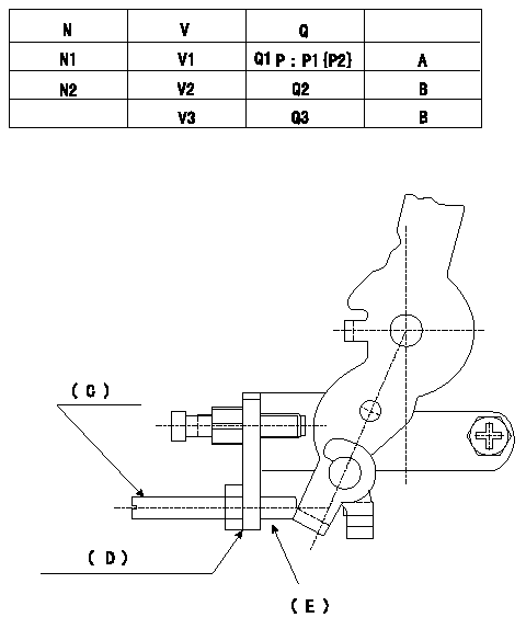
Adjusting method [applied voltage Vi, dummy bolt (C)]
1. Hold the dummy bolt (C) against the control lever at position N = N1, Q = Q1.
Fix using the lock nut.
2. When adjusting the potentiometer, position the control lever against the dummy bolt (C) and adjust the potentiometer so that the output voltage is V1 (V).
3. Remove the dummy bolt (C) after the completion of adjustment.
Confirm that the potentiometer output voltage is within the above mentioned standards between the control lever's adjusting point and the idling position.
N:Pump speed
V:Output voltage
Q:Injection quantity
P:Boost pressure
A:Adjusting point
B:Checking point
Q2:Idle
Q3:Full speed
(C): Dummy bolt
(D): Bracket for mounting the dummy bolt
(E): Part numbers of the dummy bolt and the nut
146526-3300 (bolt) 42L
013020-6040 (nut)
----------
N1=750r/min V1=4.10+-0.03V Q1=14.4+-1cm3/1,000st Vi=10V
----------
N1=750r/min N2=385r/min V1=4.1+-0.03V V2=(1.85+-0.45)V V3=(7.68+-0.83)V Q1=14.4+-1.0cm3/1,000st Q2=8.2+-2.0cm3/1,000st(Idle) Q3=Full speed Vi=10V P1=-kPa P2=-mmHg
----------
N1=750r/min V1=4.10+-0.03V Q1=14.4+-1cm3/1,000st Vi=10V
----------
N1=750r/min N2=385r/min V1=4.1+-0.03V V2=(1.85+-0.45)V V3=(7.68+-0.83)V Q1=14.4+-1.0cm3/1,000st Q2=8.2+-2.0cm3/1,000st(Idle) Q3=Full speed Vi=10V P1=-kPa P2=-mmHg
0000001901 W-CSD ADJUSTMENT
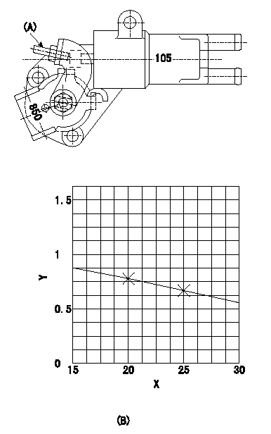
Adjustment of the W-CSD
1. Determine the timer advance angle using the graph.
2. Adjust with the screw (A) so that the timer advance angle determined in item 1 is obtained.
Y:Time lift TA (mm)
X:Temperature t (deg C)
(B): Timer stroke TA (mm)
----------
----------
(B):TA=-0.0216t+1.21
----------
----------
(B):TA=-0.0216t+1.21
0000002001 V-FICD ADJUSTMENT
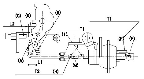
Adjustment of the V-FICD
1. Mount the V-FICD after the completion of potentiometer adjustment.
2. Confirm that the clearance between the control lever (B) and the actuator rod (A) is at least L1.
3. Insert the L2 shim between the control lever (D) and the idle set screw (C).
4. Adjust with the stroke adjusting screw (E) so that the actuator can make a full stroke.
Fix using the nut (F).
Note
When adjustment is not possible using the stroke adjusting screw (F), move the actuator rod position using (G), (H) and (I).
Adjust again the stroke with (E) and (F).
5. Apply the negative pressure of P1{P2} to the actuator. Confirm that it moves through its full stroke.
6. After releasing negative pressure, re-confirm that the clearance between (A) and (B) is L3.
----------
L1=1mm L2=3.4+-0.1mm L3=1+1mm P1=-53.3kPa P2=-400mmHg
----------
L3=1+1mm L2=3.4+-0.1mm T1=-Nm(-kgfm) T2=-Nm(-kgfm)
----------
L1=1mm L2=3.4+-0.1mm L3=1+1mm P1=-53.3kPa P2=-400mmHg
----------
L3=1+1mm L2=3.4+-0.1mm T1=-Nm(-kgfm) T2=-Nm(-kgfm)
Have questions with 104746-5151?
Group cross 104746-5151 ZEXEL
Isuzu
104746-5151
F 01G 09W 00H
8972888381
INJECTION-PUMP ASSEMBLY
4JA1
4JA1