Rating:
Information injection-pump assembly
BOSCH
9 400 614 279
9400614279
ZEXEL
101491-0354
1014910354
ISUZU
8944644695
8944644695
Service parts 101491-0354 INJECTION-PUMP ASSEMBLY:
1.
_
6.
COUPLING PLATE
7.
COUPLING PLATE
8.
_
9.
_
11.
Nozzle and Holder
8-94151-865-1
12.
Open Pre:MPa(Kqf/cm2)
18.1{185}

15.
NOZZLE SET
Cross reference number
BOSCH
9 400 614 279
9400614279
ZEXEL
101491-0354
1014910354
ISUZU
8944644695
8944644695
Zexel num
Bosch num
Firm num
Name
101491-0354
9 400 614 279
8944644695 ISUZU
INJECTION-PUMP ASSEMBLY
4BC2 * K
4BC2 * K
Calibration Data:
Adjustment conditions
Test oil
1404 Test oil ISO4113 or {SAEJ967d}
1404 Test oil ISO4113 or {SAEJ967d}
Test oil temperature
degC
40
40
45
Nozzle and nozzle holder
105780-8140
Bosch type code
EF8511/9A
Nozzle
105780-0000
Bosch type code
DN12SD12T
Nozzle holder
105780-2080
Bosch type code
EF8511/9
Opening pressure
MPa
17.2
Opening pressure
kgf/cm2
175
Injection pipe
Outer diameter - inner diameter - length (mm) mm 6-2-600
Outer diameter - inner diameter - length (mm) mm 6-2-600
Tester oil delivery pressure
kPa
157
157
157
Tester oil delivery pressure
kgf/cm2
1.6
1.6
1.6
Direction of rotation (viewed from drive side)
Right R
Right R
Injection timing adjustment
Direction of rotation (viewed from drive side)
Right R
Right R
Injection order
1-3-4-2
Pre-stroke
mm
3.4
3.35
3.45
Beginning of injection position
Drive side NO.1
Drive side NO.1
Difference between angles 1
Cal 1-3 deg. 90 89.5 90.5
Cal 1-3 deg. 90 89.5 90.5
Difference between angles 2
Cal 1-4 deg. 180 179.5 180.5
Cal 1-4 deg. 180 179.5 180.5
Difference between angles 3
Cyl.1-2 deg. 270 269.5 270.5
Cyl.1-2 deg. 270 269.5 270.5
Injection quantity adjustment
Adjusting point
-
Rack position
10.5
Pump speed
r/min
1100
1100
1100
Average injection quantity
mm3/st.
56
54.4
57.6
Max. variation between cylinders
%
0
-3.5
3.5
Basic
*
Fixing the rack
*
Standard for adjustment of the maximum variation between cylinders
*
Injection quantity adjustment_02
Adjusting point
-
Rack position
9.7+-0.5
Pump speed
r/min
300
300
300
Average injection quantity
mm3/st.
9.5
8
11
Max. variation between cylinders
%
0
-10
10
Fixing the rack
*
Standard for adjustment of the maximum variation between cylinders
*
Remarks
Adjust only variation between cylinders; adjust governor according to governor specifications.
Adjust only variation between cylinders; adjust governor according to governor specifications.
Injection quantity adjustment_03
Adjusting point
A
Rack position
R1(10.5)
Pump speed
r/min
1100
1100
1100
Average injection quantity
mm3/st.
56
55
57
Basic
*
Fixing the lever
*
Injection quantity adjustment_04
Adjusting point
B
Rack position
R1-0.05
Pump speed
r/min
1800
1800
1800
Average injection quantity
mm3/st.
55
51.8
58.2
Fixing the lever
*
Injection quantity adjustment_05
Adjusting point
C
Rack position
R1-0.1
Pump speed
r/min
700
700
700
Average injection quantity
mm3/st.
42.1
38.9
45.3
Fixing the lever
*
Injection quantity adjustment_06
Adjusting point
D
Rack position
R1+0.5
Pump speed
r/min
500
500
500
Average injection quantity
mm3/st.
41.7
37.7
45.7
Fixing the lever
*
Injection quantity adjustment_07
Adjusting point
I
Rack position
-
Pump speed
r/min
100
100
100
Average injection quantity
mm3/st.
56
51
61
Fixing the lever
*
Rack limit
*
Timer adjustment
Pump speed
r/min
1650--
Advance angle
deg.
0
0
0
Remarks
Start
Start
Timer adjustment_02
Pump speed
r/min
1600
Advance angle
deg.
0.6
Timer adjustment_03
Pump speed
r/min
1800
Advance angle
deg.
3
2.5
3.5
Timer adjustment_04
Pump speed
r/min
1900
Advance angle
deg.
4.5
4
5
Timer adjustment_05
Pump speed
r/min
-
Advance angle
deg.
5
5
5
Remarks
Measure the actual speed, stop
Measure the actual speed, stop
Test data Ex:
Governor adjustment
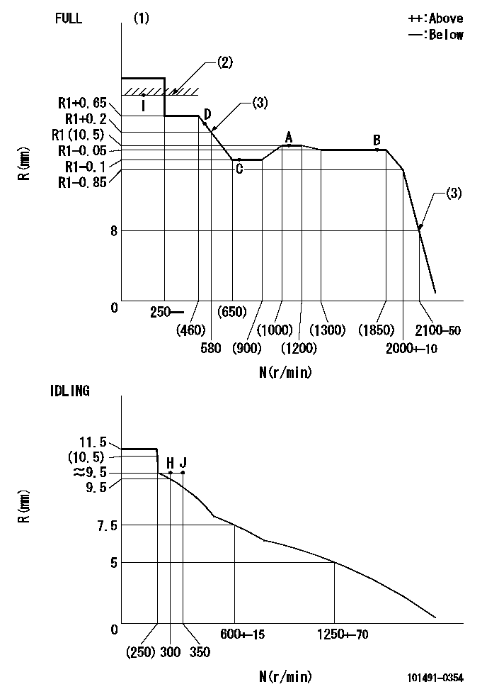
N:Pump speed
R:Rack position (mm)
(1)Torque cam stamping: T1
(2)RACK LIMIT
(3)The torque cam setting and high idle must be set when speed is increasing from low to high (because of hysterisis).
----------
T1=A73
----------
----------
T1=A73
----------
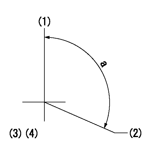
Speed control lever angle
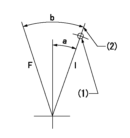
F:Full speed
I:Idle
(1)Use the hole at R = aa
(2)Stopper bolt set position 'H'
----------
aa=50mm
----------
a=29deg+-5deg b=41deg+-3deg
----------
aa=50mm
----------
a=29deg+-5deg b=41deg+-3deg
0000001501 MICRO SWITCH
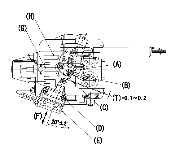
(A) Cam fixing bolt
(B) Screw B
(C) Cam (select)
(D) Microswitch fixing bolt
(E) Microswitch
(F) Adjusting direction
(G) Idle adjusting bolt
(H) Full speed adjusting bolt
(T) Distance
Adjustment of the micro-switch
1. Adjustment specifications
(1)Full side switch ON position
When a thickness gauge is inserted between the speed lever and the full speed adjusting bolt and the speed lever is moved from the idle side to the full side.
Confirm no continuity using a thickness gauge t = 0.3.
Confirm no continuity using a thickness gauge t = 0.1.
(2)Idle side switch ON.
When a thickness gauge is inserted between the speed lever and the idle adjusting bolt and the speed lever is moved from the full side to the idle side.
Confirm no continuity using a thickness gauge t = 1.1.
Confirm no continuity using a thickness gauge t = 0.5.
2. Procedures for adjustment
(1)Standard position for Cam (159226-8100), stamping mark M, is explained in above illustration.
(2)Fix the microswitch body in the position shown in the figure above. (The microswitch is free.)
(3)Full side adjustment
Adjust using screw B to satisfy the adjustment specifications (1) above.
(4)Idle side confirmation
Move the speed lever from the full side to the idle side and confirm the above adjustment specification (2).
(5)When the idle side is not as specified, replace the cam (stamping S or L) and repeat adjustment from procedure 2.(2) above.
----------
----------
----------
----------
Timing setting
(1)Pump vertical direction
(2)Position of gear mark 'CC' at No 1 cylinder's beginning of injection
(3)B.T.D.C.: aa
(4)-
----------
aa=16deg
----------
a=(100deg)
----------
aa=16deg
----------
a=(100deg)
Have questions with 101491-0354?
Group cross 101491-0354 ZEXEL
Isuzu
101491-0354
9 400 614 279
8944644695
INJECTION-PUMP ASSEMBLY
4BC2
4BC2