
Rating:
Information injection-pump assembly
ZEXEL
106971-3213
1069713213
HINO
220009303A
220009303a
Service parts 106971-3213 INJECTION-PUMP ASSEMBLY:
1.
_
7.
COUPLING PLATE
8.
_
9.
_
11.
Nozzle and Holder
23600-2750A
12.
Open Pre:MPa(Kqf/cm2)
14.7{150}/21.6{220}
14.
NOZZLE
Include in #1:
106971-3213
as INJECTION-PUMP ASSEMBLY
Cross reference number
ZEXEL
106971-3213
1069713213
HINO
220009303A
220009303a
Zexel num
Bosch num
Firm num
Name
Calibration Data:
Adjustment conditions
Test oil
1404 Test oil ISO4113 or {SAEJ967d}
1404 Test oil ISO4113 or {SAEJ967d}
Test oil temperature
degC
40
40
45
Nozzle and nozzle holder
105780-8250
Bosch type code
1 688 901 101
Nozzle
105780-0120
Bosch type code
1 688 901 990
Nozzle holder
105780-2190
Opening pressure
MPa
20.7
Opening pressure
kgf/cm2
211
Injection pipe
Outer diameter - inner diameter - length (mm) mm 8-3-600
Outer diameter - inner diameter - length (mm) mm 8-3-600
Overflow valve
134424-4120
Overflow valve opening pressure
kPa
255
221
289
Overflow valve opening pressure
kgf/cm2
2.6
2.25
2.95
Tester oil delivery pressure
kPa
255
255
255
Tester oil delivery pressure
kgf/cm2
2.6
2.6
2.6
RED3 control unit part number
407910-2
470
RED3 rack sensor specifications
mm
15
Direction of rotation (viewed from drive side)
Right R
Right R
Injection timing adjustment
Direction of rotation (viewed from drive side)
Right R
Right R
Injection order
1-10-9-4
-3-6-5-8
-7-2
Pre-stroke
mm
4.2
4.14
4.2
Beginning of injection position
Governor side NO.1
Governor side NO.1
Difference between angles 1
Cal 1-10 deg. 27 26.75 27.25
Cal 1-10 deg. 27 26.75 27.25
Difference between angles 2
Cal 1-9 deg. 72 71.75 72.25
Cal 1-9 deg. 72 71.75 72.25
Difference between angles 3
Cal 1-4 deg. 99 98.75 99.25
Cal 1-4 deg. 99 98.75 99.25
Difference between angles 4
Cal 1-3 deg. 144 143.75 144.25
Cal 1-3 deg. 144 143.75 144.25
Difference between angles 5
Cal 1-6 deg. 171 170.75 171.25
Cal 1-6 deg. 171 170.75 171.25
Difference between angles 6
Cal 1-5 deg. 216 215.75 216.25
Cal 1-5 deg. 216 215.75 216.25
Difference between angles 7
Cal 1-8 deg. 243 242.75 243.25
Cal 1-8 deg. 243 242.75 243.25
Difference between angles 8
Cal 1-7 deg. 288 287.75 288.25
Cal 1-7 deg. 288 287.75 288.25
Difference between angles 9
Cyl.1-2 deg. 315 314.75 315.25
Cyl.1-2 deg. 315 314.75 315.25
Injection quantity adjustment
Rack position
(12.8)
Vist
V
1.45
1.45
1.45
Pump speed
r/min
700
700
700
Average injection quantity
mm3/st.
135.5
133.5
137.5
Max. variation between cylinders
%
0
-4
4
Basic
*
Injection quantity adjustment_02
Rack position
(8.4)
Vist
V
2.31
2.25
2.37
Pump speed
r/min
410
410
410
Average injection quantity
mm3/st.
18
15
21
Max. variation between cylinders
%
0
-10
10
Governor adjustment
Pump speed
r/min
720--
Advance angle
deg.
0
0
0
Load
2/5
Remarks
Start
Start
Governor adjustment_02
Pump speed
r/min
670
Advance angle
deg.
0.3
Load
2/5
Governor adjustment_03
Pump speed
r/min
(790--)
Advance angle
deg.
2
1.7
2.3
Load
5/5
Governor adjustment_04
Pump speed
r/min
870
Advance angle
deg.
2
1.7
2.3
Load
4/5
Governor adjustment_05
Pump speed
r/min
(960--)
Advance angle
deg.
2
1.7
2.3
Load
5/5
Governor adjustment_06
Pump speed
r/min
1080-50
Advance angle
deg.
6.75
6.45
7.05
Load
5/5
Remarks
Finish
Finish
Test data Ex:
Speed control lever angle
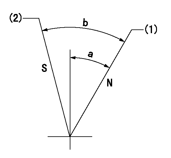
N:Pump normal
S:Stop the pump.
(1)Rack position = aa
(2)Rack position bb
----------
aa=16mm bb=1mm
----------
a=19deg+-5deg b=29deg+-5deg
----------
aa=16mm bb=1mm
----------
a=19deg+-5deg b=29deg+-5deg
0000000901
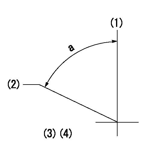
(1)Pump vertical direction
(2)Coupling's key groove position at No 1 cylinder's beginning of injection
(3)-
(4)-
----------
----------
a=(80deg)
----------
----------
a=(80deg)
Stop lever angle
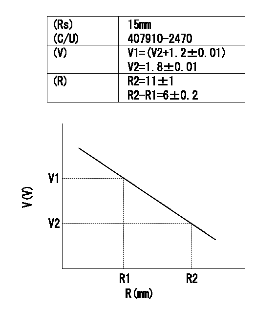
(Rs) rack sensor specifications
(C/U) control unit part number
(V) Rack sensor output voltage
(R) Rack position (mm)
1. Confirming governor output characteristics (rack 15 mm, span 6 mm)
(1)When the output voltages of the rack sensor are V1 and V2, check that the rack positions R1 and R2 in the table above are satisfied.
----------
----------
----------
----------