Information injection-pump assembly
ZEXEL
106871-5430
1068715430

Rating:
Service parts 106871-5430 INJECTION-PUMP ASSEMBLY:
1.
_
7.
COUPLING PLATE
8.
_
9.
_
11.
Nozzle and Holder
16600-97112
12.
Open Pre:MPa(Kqf/cm2)
17.7{180}/22.6{230}
14.
NOZZLE
Include in #1:
106871-5430
as INJECTION-PUMP ASSEMBLY
Cross reference number
ZEXEL
106871-5430
1068715430
Zexel num
Bosch num
Firm num
Name
106871-5430
INJECTION-PUMP ASSEMBLY
14CD PE8P PE
14CD PE8P PE
Calibration Data:
Adjustment conditions
Test oil
1404 Test oil ISO4113 or {SAEJ967d}
1404 Test oil ISO4113 or {SAEJ967d}
Test oil temperature
degC
40
40
45
Nozzle and nozzle holder
105780-8250
Bosch type code
1 688 901 101
Nozzle
105780-0120
Bosch type code
1 688 901 990
Nozzle holder
105780-2190
Opening pressure
MPa
20.7
Opening pressure
kgf/cm2
211
Injection pipe
Outer diameter - inner diameter - length (mm) mm 8-3-600
Outer diameter - inner diameter - length (mm) mm 8-3-600
Overflow valve
131425-0120
Overflow valve opening pressure
kPa
157
123
191
Overflow valve opening pressure
kgf/cm2
1.6
1.25
1.95
Tester oil delivery pressure
kPa
255
255
255
Tester oil delivery pressure
kgf/cm2
2.6
2.6
2.6
RED3 control unit part number
407910-3
960
RED3 rack sensor specifications
mm
19
Direction of rotation (viewed from drive side)
Right R
Right R
Injection timing adjustment
Direction of rotation (viewed from drive side)
Right R
Right R
Injection order
1-8-7-5-
4-3-6-2
Pre-stroke
mm
3.9
3.87
3.93
Beginning of injection position
Governor side NO.1
Governor side NO.1
Difference between angles 1
Cal 1-8 deg. 45 44.75 45.25
Cal 1-8 deg. 45 44.75 45.25
Difference between angles 2
Cal 1-7 deg. 90 89.75 90.25
Cal 1-7 deg. 90 89.75 90.25
Difference between angles 3
Cal 1-5 deg. 135 134.75 135.25
Cal 1-5 deg. 135 134.75 135.25
Difference between angles 4
Cal 1-4 deg. 180 179.75 180.25
Cal 1-4 deg. 180 179.75 180.25
Difference between angles 5
Cal 1-3 deg. 225 224.75 225.25
Cal 1-3 deg. 225 224.75 225.25
Difference between angles 6
Cal 1-6 deg. 270 269.75 270.25
Cal 1-6 deg. 270 269.75 270.25
Difference between angles 7
Cyl.1-2 deg. 315 314.75 315.25
Cyl.1-2 deg. 315 314.75 315.25
Injection quantity adjustment
Rack position
(13.7)
Vist
V
1.8
1.8
1.8
Pump speed
r/min
600
600
600
Average injection quantity
mm3/st.
141.5
139.5
143.5
Max. variation between cylinders
%
0
-4
4
Basic
*
Injection quantity adjustment_02
Rack position
(9)
Vist
V
2.5
2.4
2.6
Pump speed
r/min
330
330
330
Average injection quantity
mm3/st.
16
14
18
Max. variation between cylinders
%
0
-10
10
Test data Ex:
Governor adjustment

(1)Adjusting range
(2)Step response time
(N): Speed of the pump
(L): Load
(theta) Advance angle
(Srd1) Step response time 1
(Srd2) Step response time 2
1. Adjusting conditions for the variable timer
(1)Adjust the clearance between the pickup and the protrusion to L.
----------
L=1-0.2mm N4=800r/min C4=(9deg) t1=1.7--sec. t2=1.7--sec.
----------
N1=400r/min N2=1000++r/min N3=- C1=9+-0.3deg C2=3.5++deg C3=- P1=0kPa(0kgf/cm2) P2=294kPa(3kgf/cm2) P3=392kPa(4kgf/cm2) R01=0/4load R02=4/4load R03=4/4load
----------
L=1-0.2mm N4=800r/min C4=(9deg) t1=1.7--sec. t2=1.7--sec.
----------
N1=400r/min N2=1000++r/min N3=- C1=9+-0.3deg C2=3.5++deg C3=- P1=0kPa(0kgf/cm2) P2=294kPa(3kgf/cm2) P3=392kPa(4kgf/cm2) R01=0/4load R02=4/4load R03=4/4load
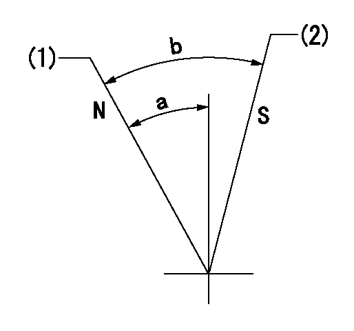
Speed control lever angle

N:Pump normal
S:Stop the pump.
(1)Rack position = aa
(2)Rack position bb
----------
aa=20mm bb=1mm
----------
a=27deg+-5deg b=37deg+-5deg
----------
aa=20mm bb=1mm
----------
a=27deg+-5deg b=37deg+-5deg
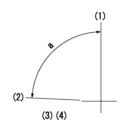
0000000901

(1)Pump vertical direction
(2)Position of the coupling's key groove at the beginning of injection of the No. 8 cylinder.
(3)-
(4)-
----------
----------
a=(90deg)
----------
----------
a=(90deg)
Stop lever angle

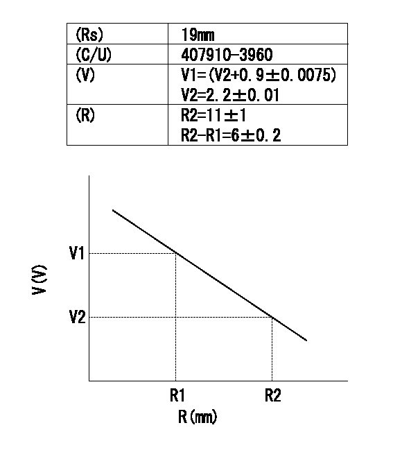
(Rs) rack sensor specifications
(C/U) control unit part number
(V) Rack sensor output voltage
(R) Rack position (mm)
1. Confirming governor output characteristics (rack 19 mm, span 6 mm)
(1)When the output voltages of the rack sensor are V1 and V2, check that the rack positions R1 and R2 in the table above are satisfied.
----------
----------
----------
----------
Information:
Table 1
Part Number Description
370-5513 Fuel Line
370-5516 Fuel Injection Line As
370-5517 Fuel Injection Line As
370-5518 Fuel Injection Line As
393-5467 Fuel Line
393-5468 Fuel Line
396-2606 Fuel Line
396-2607 Fuel Line
396-2608 Fuel Line
396-2609 Fuel Line Any of the part numbers listed in Table 1 may be affected.
Do not operate or work on this product unless you have read and understood the instruction and warnings in the relevant Operation and Maintenance Manuals and relevant service literature. Failure to follow the instructions or heed the warnings could result in injury or death. Proper care is your responsibility.
If any of the fuel injection lines are leaking, Caterpillar recommends replacing all high-pressure fuel lines on the engine. Refer to Disassembly and Assembly, Fuel Injection Lines - Remove and Disassembly and Assembly, Fuel Injection Lines - Install.
Have questions with 106871-5430?
Group cross 106871-5430 ZEXEL
Nissan-Diesel
Nissan-Diesel
Nissan-Diesel
106871-5430
INJECTION-PUMP ASSEMBLY