
Rating:
Information injection-pump assembly
BOSCH
9 400 610 123
9400610123
ZEXEL
106691-4031
1066914031
KOMATSU
6151712720
6151712720
Service parts 106691-4031 INJECTION-PUMP ASSEMBLY:
1.
_
7.
COUPLING PLATE
8.
_
9.
_
11.
Nozzle and Holder
6151-11-3101
12.
Open Pre:MPa(Kqf/cm2)
24.5{250}
15.
NOZZLE SET
Include in #1:
106691-4031
as INJECTION-PUMP ASSEMBLY
Cross reference number
BOSCH
9 400 610 123
9400610123
ZEXEL
106691-4031
1066914031
KOMATSU
6151712720
6151712720
Zexel num
Bosch num
Firm num
Name
9 400 610 123
6151712720 KOMATSU
INJECTION-PUMP ASSEMBLY
S6D125 * K 14CA PE6P,6PD PE
S6D125 * K 14CA PE6P,6PD PE
Calibration Data:
Adjustment conditions
Test oil
1404 Test oil ISO4113 or {SAEJ967d}
1404 Test oil ISO4113 or {SAEJ967d}
Test oil temperature
degC
40
40
45
Nozzle and nozzle holder
105780-8140
Bosch type code
EF8511/9A
Nozzle
105780-0000
Bosch type code
DN12SD12T
Nozzle holder
105780-2080
Bosch type code
EF8511/9
Opening pressure
MPa
17.2
Opening pressure
kgf/cm2
175
Injection pipe
Outer diameter - inner diameter - length (mm) mm 8-3-600
Outer diameter - inner diameter - length (mm) mm 8-3-600
Overflow valve
132424-0620
Overflow valve opening pressure
kPa
157
123
191
Overflow valve opening pressure
kgf/cm2
1.6
1.25
1.95
Tester oil delivery pressure
kPa
157
157
157
Tester oil delivery pressure
kgf/cm2
1.6
1.6
1.6
Direction of rotation (viewed from drive side)
Left L
Left L
Injection timing adjustment
Direction of rotation (viewed from drive side)
Left L
Left L
Injection order
1-5-3-6-
2-4
Pre-stroke
mm
3.75
3.7
3.8
Beginning of injection position
Drive side NO.1
Drive side NO.1
Difference between angles 1
Cal 1-5 deg. 60 59.5 60.5
Cal 1-5 deg. 60 59.5 60.5
Difference between angles 2
Cal 1-3 deg. 120 119.5 120.5
Cal 1-3 deg. 120 119.5 120.5
Difference between angles 3
Cal 1-6 deg. 180 179.5 180.5
Cal 1-6 deg. 180 179.5 180.5
Difference between angles 4
Cyl.1-2 deg. 240 239.5 240.5
Cyl.1-2 deg. 240 239.5 240.5
Difference between angles 5
Cal 1-4 deg. 300 299.5 300.5
Cal 1-4 deg. 300 299.5 300.5
Injection quantity adjustment
Adjusting point
A
Rack position
7.5
Pump speed
r/min
1100
1100
1100
Average injection quantity
mm3/st.
123.8
121.8
125.8
Max. variation between cylinders
%
0
-3
3
Basic
*
Fixing the lever
*
Injection quantity adjustment_02
Adjusting point
B
Rack position
8.1
Pump speed
r/min
700
700
700
Average injection quantity
mm3/st.
137.1
135.1
139.1
Max. variation between cylinders
%
0
-4
4
Fixing the lever
*
Injection quantity adjustment_03
Adjusting point
C
Rack position
4+-0.5
Pump speed
r/min
325
325
325
Average injection quantity
mm3/st.
13.4
11.9
14.9
Max. variation between cylinders
%
0
-15
15
Fixing the rack
*
Boost compensator adjustment
Pump speed
r/min
650
650
650
Rack position
6.6
Boost pressure
kPa
7.3
6
8.6
Boost pressure
mmHg
55
45
65
Boost compensator adjustment_02
Pump speed
r/min
650
650
650
Rack position
7.3
Boost pressure
kPa
10.7
10.7
10.7
Boost pressure
mmHg
80
80
80
Boost compensator adjustment_03
Pump speed
r/min
650
650
650
Rack position
8.1
Boost pressure
kPa
21.3
14.6
28
Boost pressure
mmHg
160
110
210
Timer adjustment
Pump speed
r/min
700--
Advance angle
deg.
0
0
0
Remarks
Start
Start
Timer adjustment_02
Pump speed
r/min
650
Advance angle
deg.
0.5
Timer adjustment_03
Pump speed
r/min
1050
Advance angle
deg.
3
2.5
3.5
Remarks
Finish
Finish
Test data Ex:
Governor adjustment
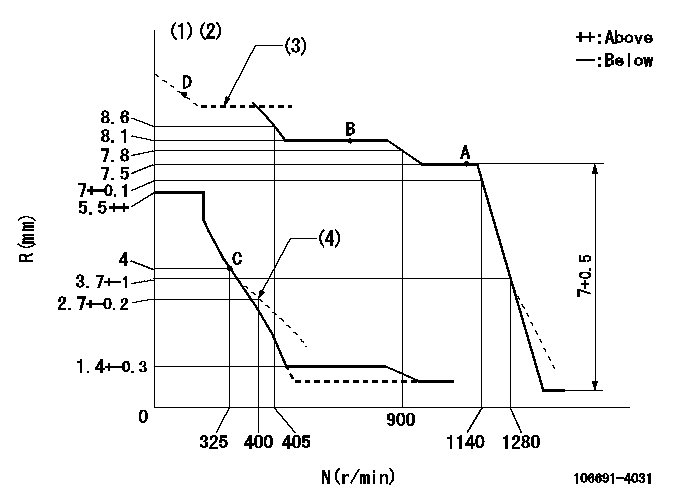
N:Pump speed
R:Rack position (mm)
(1)Tolerance for racks not indicated: +-0.05mm.
(2)Supply with excess fuel lever not operating.
(3)After adjusting the boost compensator, adjust the boost pressure at N = N1 and set R = R1 using the boost compensator screw (boost pressure 0).
(4)Damper spring setting
----------
N1=300r/min R1=9.5+-0.2mm
----------
----------
N1=300r/min R1=9.5+-0.2mm
----------
Speed control lever angle
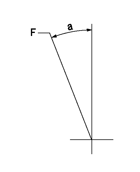
F:Full speed
----------
----------
a=23deg+-5deg
----------
----------
a=23deg+-5deg
0000000901
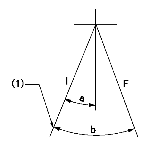
F:Full load
I:Idle
(1)Stopper bolt setting
----------
----------
a=15.5deg+-5deg b=36deg+-3deg
----------
----------
a=15.5deg+-5deg b=36deg+-3deg
Stop lever angle
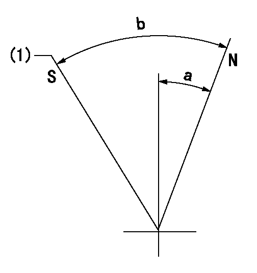
N:Pump normal
S:Stop the pump.
(1)Rack position = aa or less (confirm).
----------
aa=1.5mm
----------
a=33deg+-5deg b=73deg+-5deg
----------
aa=1.5mm
----------
a=33deg+-5deg b=73deg+-5deg
Timing setting
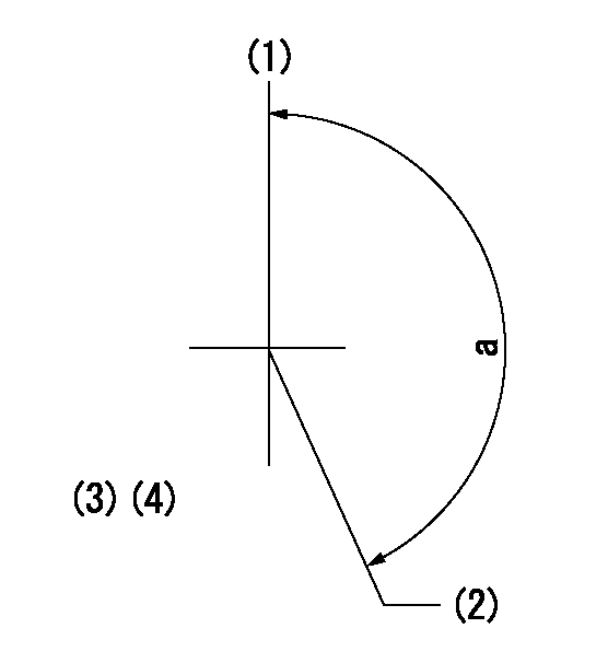
(1)Pump vertical direction
(2)Coupling's key groove position at No 1 cylinder's beginning of injection
(3)-
(4)-
----------
----------
a=(150deg)
----------
----------
a=(150deg)