
Rating:
Information injection-pump assembly
ZEXEL
106682-9190
1066829190
KOMATSU
6212711310
6212711310
Service parts 106682-9190 INJECTION-PUMP ASSEMBLY:
1.
_
5.
AUTOM. ADVANCE MECHANIS
7.
COUPLING PLATE
8.
_
9.
_
11.
Nozzle and Holder
6212-11-3202
12.
Open Pre:MPa(Kqf/cm2)
24.5{250}
15.
NOZZLE SET
Include in #1:
106682-9190
as INJECTION-PUMP ASSEMBLY
Cross reference number
ZEXEL
106682-9190
1066829190
KOMATSU
6212711310
6212711310
Zexel num
Bosch num
Firm num
Name
Calibration Data:
Adjustment conditions
Test oil
1404 Test oil ISO4113 or {SAEJ967d}
1404 Test oil ISO4113 or {SAEJ967d}
Test oil temperature
degC
40
40
45
Nozzle and nozzle holder
105780-8130
Bosch type code
EFEP215A
Nozzle
105780-0050
Bosch type code
DN6TD119NP1T
Nozzle holder
105780-2090
Bosch type code
EFEP215
Opening pressure
MPa
17.2
Opening pressure
kgf/cm2
175
Injection pipe
Outer diameter - inner diameter - length (mm) mm 8-4-1000
Outer diameter - inner diameter - length (mm) mm 8-4-1000
Overflow valve
131424-7120
Overflow valve opening pressure
kPa
255
221
289
Overflow valve opening pressure
kgf/cm2
2.6
2.25
2.95
Tester oil delivery pressure
kPa
157
157
157
Tester oil delivery pressure
kgf/cm2
1.6
1.6
1.6
Direction of rotation (viewed from drive side)
Right R
Right R
Injection timing adjustment
Direction of rotation (viewed from drive side)
Right R
Right R
Injection order
1-5-3-6-
2-4
Pre-stroke
mm
3
2.95
3.05
Beginning of injection position
Drive side NO.1
Drive side NO.1
Difference between angles 1
Cal 1-5 deg. 60 59.5 60.5
Cal 1-5 deg. 60 59.5 60.5
Difference between angles 2
Cal 1-3 deg. 120 119.5 120.5
Cal 1-3 deg. 120 119.5 120.5
Difference between angles 3
Cal 1-6 deg. 180 179.5 180.5
Cal 1-6 deg. 180 179.5 180.5
Difference between angles 4
Cyl.1-2 deg. 240 239.5 240.5
Cyl.1-2 deg. 240 239.5 240.5
Difference between angles 5
Cal 1-4 deg. 300 299.5 300.5
Cal 1-4 deg. 300 299.5 300.5
Injection quantity adjustment
Adjusting point
A
Rack position
14.4
Pump speed
r/min
1000
1000
1000
Average injection quantity
mm3/st.
352
349
355
Max. variation between cylinders
%
0
-3
3
Basic
*
Fixing the lever
*
Boost pressure
kPa
49.3
49.3
Boost pressure
mmHg
370
370
Injection quantity adjustment_02
Adjusting point
B
Rack position
7.8+-0.5
Pump speed
r/min
410
410
410
Average injection quantity
mm3/st.
22
20.5
23.5
Max. variation between cylinders
%
0
-15
15
Fixing the rack
*
Boost pressure
kPa
0
0
0
Boost pressure
mmHg
0
0
0
Injection quantity adjustment_03
Adjusting point
E
Rack position
16+0.2
Pump speed
r/min
100
100
100
Average injection quantity
mm3/st.
335
315
355
Fixing the lever
*
Boost pressure
kPa
0
0
0
Boost pressure
mmHg
0
0
0
Rack limit
*
Boost compensator adjustment
Pump speed
r/min
700
700
700
Rack position
12.4
Boost pressure
kPa
13.3
6.6
20
Boost pressure
mmHg
100
50
150
Boost compensator adjustment_02
Pump speed
r/min
700
700
700
Rack position
15.4
Boost pressure
kPa
44
41.3
46.7
Boost pressure
mmHg
300
280
320
Test data Ex:
Governor adjustment
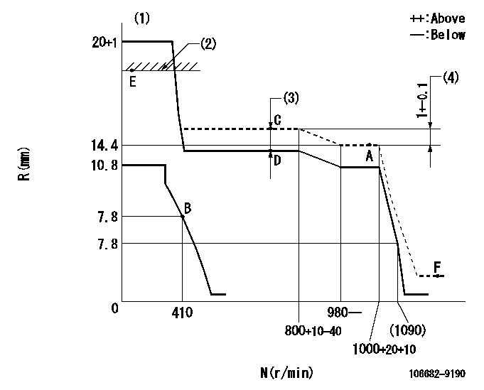
N:Pump speed
R:Rack position (mm)
(1)Notch fixed: K
(2)RACK LIMIT: RAL
(3)Boost compensator stroke: BCL
(4)Rack difference between N = N1 and N = N2
----------
K=21 RAL=16+0.2mm BCL=3+-0.1mm N1=1000r/min N2=700r/min
----------
----------
K=21 RAL=16+0.2mm BCL=3+-0.1mm N1=1000r/min N2=700r/min
----------
Speed control lever angle
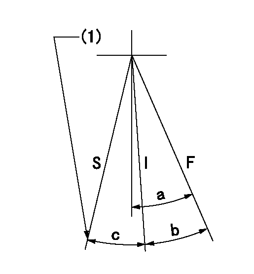
F:Full speed
I:Idle
S:Stop
(1)Stopper bolt setting
----------
----------
a=30deg+-5deg b=24deg+-5deg c=21.5deg+-5deg
----------
----------
a=30deg+-5deg b=24deg+-5deg c=21.5deg+-5deg
Stop lever angle
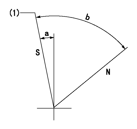
N:Pump normal
S:Stop the pump.
(1)Pump speed aa and rack position bb (to be sealed at delivery)
----------
aa=0r/min bb=1-0.2mm
----------
a=29deg+-5deg b=(73deg)
----------
aa=0r/min bb=1-0.2mm
----------
a=29deg+-5deg b=(73deg)
0000001501 LEVER
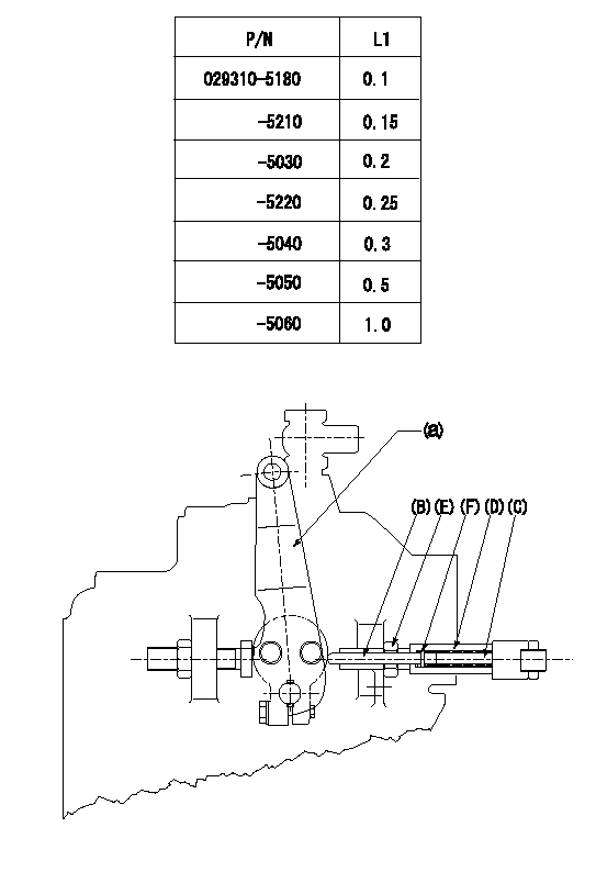
Speed lever adjustment
1. (1) For idling hold the speed lever (a) against the push rod (B).
(2)At this time, confirm that the spring (C) is not bent by the operating torque of the speed lever.
2. (1) To stop, bend the spring (C) using the speed lever.
(2)Set so that the rack position is L2.
(3)Set and fix using lock nut (E) so that it contacts the guide screw (D).
(4)Adjust rack position at this time using shim (F).
3. Confirm that the speed lever returns to the idling position when pulled in the stop direction and then released.
----------
L2=0.2~2mm
----------
----------
L2=0.2~2mm
----------
Timing setting
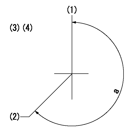
(1)Pump vertical direction
(2)Coupling's key groove position at No 1 cylinder's beginning of injection
(3)-
(4)-
----------
----------
a=(260deg)
----------
----------
a=(260deg)