
Rating:
Information injection-pump assembly
BOSCH
F 019 Z20 172
f019z20172
ZEXEL
106682-3121
1066823121
HINO
220206471A
220206471a
Service parts 106682-3121 INJECTION-PUMP ASSEMBLY:
1.
_
5.
AUTOM. ADVANCE MECHANIS
8.
_
9.
_
11.
Nozzle and Holder
12.
Open Pre:MPa(Kqf/cm2)
16.7(170)/23.5(220)
14.
NOZZLE
Include in #1:
106682-3121
as INJECTION-PUMP ASSEMBLY
Cross reference number
BOSCH
F 019 Z20 172
f019z20172
ZEXEL
106682-3121
1066823121
HINO
220206471A
220206471a
Zexel num
Bosch num
Firm num
Name
106682-3121
F 019 Z20 172
220206471A HINO
INJECTION-PUMP ASSEMBLY
K13C-TI K 14CA INJECTION PUMP ASSY PE6P,6PD PE
K13C-TI K 14CA INJECTION PUMP ASSY PE6P,6PD PE
Calibration Data:
Adjustment conditions
Test oil
1404 Test oil ISO4113 or {SAEJ967d}
1404 Test oil ISO4113 or {SAEJ967d}
Test oil temperature
degC
40
40
45
Nozzle and nozzle holder
105780-8130
Bosch type code
EFEP215A
Nozzle
105780-0050
Bosch type code
DN6TD119NP1T
Nozzle holder
105780-2090
Bosch type code
EFEP215
Opening pressure
MPa
17.2
Opening pressure
kgf/cm2
175
Injection pipe
Outer diameter - inner diameter - length (mm) mm 8-4-1000
Outer diameter - inner diameter - length (mm) mm 8-4-1000
Overflow valve
131424-9020
Overflow valve opening pressure
kPa
255
221
289
Overflow valve opening pressure
kgf/cm2
2.6
2.25
2.95
Tester oil delivery pressure
kPa
255
255
255
Tester oil delivery pressure
kgf/cm2
2.6
2.6
2.6
Direction of rotation (viewed from drive side)
Left L
Left L
Injection timing adjustment
Direction of rotation (viewed from drive side)
Left L
Left L
Injection order
1-4-2-6-
3-5
Pre-stroke
mm
3.7
3.67
3.73
Beginning of injection position
Drive side NO.1
Drive side NO.1
Difference between angles 1
Cal 1-4 deg. 60 59.75 60.25
Cal 1-4 deg. 60 59.75 60.25
Difference between angles 2
Cyl.1-2 deg. 120 119.75 120.25
Cyl.1-2 deg. 120 119.75 120.25
Difference between angles 3
Cal 1-6 deg. 180 179.75 180.25
Cal 1-6 deg. 180 179.75 180.25
Difference between angles 4
Cal 1-3 deg. 240 239.75 240.25
Cal 1-3 deg. 240 239.75 240.25
Difference between angles 5
Cal 1-5 deg. 300 299.75 300.25
Cal 1-5 deg. 300 299.75 300.25
Injection quantity adjustment
Adjusting point
A
Rack position
11.9
Pump speed
r/min
900
900
900
Average injection quantity
mm3/st.
304
301
307
Max. variation between cylinders
%
0
-3
3
Basic
*
Fixing the rack
*
Boost pressure
kPa
57.3
57.3
Boost pressure
mmHg
430
430
Injection quantity adjustment_02
Adjusting point
C
Rack position
6.4+-0.5
Pump speed
r/min
360
360
360
Average injection quantity
mm3/st.
9
6
12
Max. variation between cylinders
%
0
-15
15
Fixing the rack
*
Boost pressure
kPa
0
0
0
Boost pressure
mmHg
0
0
0
Boost compensator adjustment
Pump speed
r/min
800
800
800
Rack position
R1-2.25
Boost pressure
kPa
17.3
14.6
20
Boost pressure
mmHg
130
110
150
Boost compensator adjustment_02
Pump speed
r/min
800
800
800
Rack position
R1(12.95
)
Boost pressure
kPa
44
44
44
Boost pressure
mmHg
330
330
330
Test data Ex:
Governor adjustment
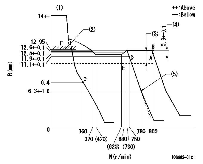
N:Pump speed
R:Rack position (mm)
(1)Notch fixed: K
(2)Boost compensator excessive fuel lever at operation: L1 (at 0 boost pressure)
(3)Boost compensator stroke: BCL
(4)Rack difference between N = N1 and N = N2
(5)Idle sub spring setting: L2.
----------
K=9 L1=13.3+-0.1mm BCL=2.25+-0.1mm N1=850r/min N2=500r/min L2=6.3-0.5mm
----------
----------
K=9 L1=13.3+-0.1mm BCL=2.25+-0.1mm N1=850r/min N2=500r/min L2=6.3-0.5mm
----------
Speed control lever angle
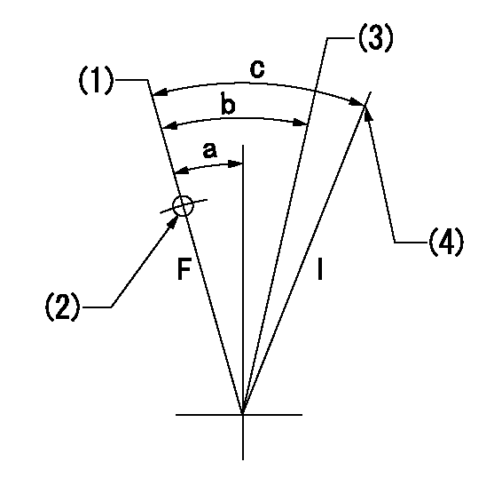
F:Full speed
I:Idle
(1)Set the pump speed at aa. ( At delivery )
(2)Use the hole at R = bb
(3)When speed is set at cc.
(4)Stopper bolt setting
----------
aa=900r/min bb=100mm cc=750r/min
----------
a=(1deg)+-5deg b=(9deg)+-5deg c=(24deg)+-5deg
----------
aa=900r/min bb=100mm cc=750r/min
----------
a=(1deg)+-5deg b=(9deg)+-5deg c=(24deg)+-5deg
Stop lever angle
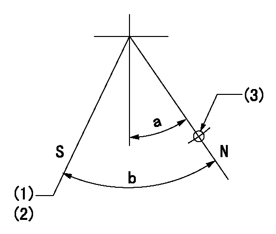
N:Pump normal
S:Stop the pump.
(1)Rack position aa or less, pump speed bb
(2)Normal stop
(3)Use the hole above R = cc
----------
aa=5.9mm bb=0r/min cc=25mm
----------
a=27deg+-5deg b=53deg+-5deg
----------
aa=5.9mm bb=0r/min cc=25mm
----------
a=27deg+-5deg b=53deg+-5deg
0000001101
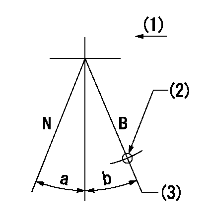
N:Normal
B:When boosted
(1)Drive side
(2)Use the hole at R = aa
(3)Rack position = bb (point F; at boost pressure = 0)
----------
aa=50mm bb=13.3+-0.1mm
----------
a=(15deg) b=(10deg)
----------
aa=50mm bb=13.3+-0.1mm
----------
a=(15deg) b=(10deg)
Timing setting

(1)Pump vertical direction
(2)Coupling's key groove position at No 1 cylinder's beginning of injection
(3)B.T.D.C.: aa
(4)-
----------
aa=16deg
----------
a=(3deg)
----------
aa=16deg
----------
a=(3deg)
Have questions with 106682-3121?
Group cross 106682-3121 ZEXEL
Hino
106682-3121
F 019 Z20 172
220206471A
INJECTION-PUMP ASSEMBLY
K13C-TI
K13C-TI