
Rating:
Information injection-pump assembly
BOSCH
9 400 617 525
9400617525
ZEXEL
106682-3102
1066823102
HINO
220206152A
220206152a
Service parts 106682-3102 INJECTION-PUMP ASSEMBLY:
1.
_
5.
AUTOM. ADVANCE MECHANIS
8.
_
9.
_
11.
Nozzle and Holder
23600-3440A
12.
Open Pre:MPa(Kqf/cm2)
17.7{180}/21.6{220}
14.
NOZZLE
Include in #1:
106682-3102
as INJECTION-PUMP ASSEMBLY
Cross reference number
BOSCH
9 400 617 525
9400617525
ZEXEL
106682-3102
1066823102
HINO
220206152A
220206152a
Zexel num
Bosch num
Firm num
Name
106682-3102
9 400 617 525
220206152A HINO
INJECTION-PUMP ASSEMBLY
P11B-TI K 14CA INJECTION PUMP ASSY PE6P,6PD PE
P11B-TI K 14CA INJECTION PUMP ASSY PE6P,6PD PE
Calibration Data:
Adjustment conditions
Test oil
1404 Test oil ISO4113 or {SAEJ967d}
1404 Test oil ISO4113 or {SAEJ967d}
Test oil temperature
degC
40
40
45
Nozzle and nozzle holder
105780-8130
Bosch type code
EFEP215A
Nozzle
105780-0050
Bosch type code
DN6TD119NP1T
Nozzle holder
105780-2090
Bosch type code
EFEP215
Opening pressure
MPa
17.2
Opening pressure
kgf/cm2
175
Injection pipe
Outer diameter - inner diameter - length (mm) mm 8-4-1000
Outer diameter - inner diameter - length (mm) mm 8-4-1000
Overflow valve
134424-0820
Overflow valve opening pressure
kPa
127
107
147
Overflow valve opening pressure
kgf/cm2
1.3
1.1
1.5
Tester oil delivery pressure
kPa
157
157
157
Tester oil delivery pressure
kgf/cm2
1.6
1.6
1.6
Direction of rotation (viewed from drive side)
Right R
Right R
Injection timing adjustment
Direction of rotation (viewed from drive side)
Right R
Right R
Injection order
1-4-2-6-
3-5
Pre-stroke
mm
3.3
3.27
3.33
Beginning of injection position
Drive side NO.1
Drive side NO.1
Difference between angles 1
Cal 1-4 deg. 60 59.75 60.25
Cal 1-4 deg. 60 59.75 60.25
Difference between angles 2
Cyl.1-2 deg. 120 119.75 120.25
Cyl.1-2 deg. 120 119.75 120.25
Difference between angles 3
Cal 1-6 deg. 180 179.75 180.25
Cal 1-6 deg. 180 179.75 180.25
Difference between angles 4
Cal 1-3 deg. 240 239.75 240.25
Cal 1-3 deg. 240 239.75 240.25
Difference between angles 5
Cal 1-5 deg. 300 299.75 300.25
Cal 1-5 deg. 300 299.75 300.25
Injection quantity adjustment
Adjusting point
A
Rack position
14.7
Pump speed
r/min
1150
1150
1150
Average injection quantity
mm3/st.
429
426
432
Max. variation between cylinders
%
0
-3
3
Basic
*
Fixing the lever
*
Boost pressure
kPa
200
200
Boost pressure
mmHg
1500
1500
Injection quantity adjustment_02
Adjusting point
C
Rack position
6.1+-0.5
Pump speed
r/min
285
285
285
Average injection quantity
mm3/st.
11
9
13
Max. variation between cylinders
%
0
-15
15
Fixing the rack
*
Boost pressure
kPa
0
0
0
Boost pressure
mmHg
0
0
0
Injection quantity adjustment_03
Adjusting point
D
Rack position
R1(10.8)
Pump speed
r/min
700
700
700
Average injection quantity
mm3/st.
191
188
194
Fixing the lever
*
Boost pressure
kPa
0
0
0
Boost pressure
mmHg
0
0
0
Boost compensator adjustment
Pump speed
r/min
700
700
700
Rack position
R1(10.8)
Boost pressure
kPa
41.3
38.6
44
Boost pressure
mmHg
310
290
330
Boost compensator adjustment_02
Pump speed
r/min
700
700
700
Rack position
R2(14.7)
Boost pressure
kPa
187
187
187
Boost pressure
mmHg
1400
1400
1400
Test data Ex:
Governor adjustment
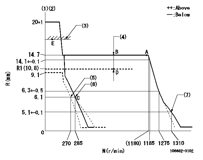
N:Pump speed
R:Rack position (mm)
(1)Target notch: K
(2)Tolerance for racks not indicated: +-0.05mm.
(3)Boost compensator excessive fuel lever at operation: L1 (at 0 boost pressure)
(4)Boost compensator stroke: BCL
(5)Set idle sub-spring
(6)Main spring setting
(7)Damper spring setting
----------
K=14 L1=16+-0.1mm BCL=(3.9)mm
----------
----------
K=14 L1=16+-0.1mm BCL=(3.9)mm
----------
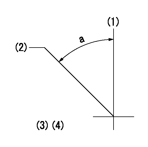
Speed control lever angle
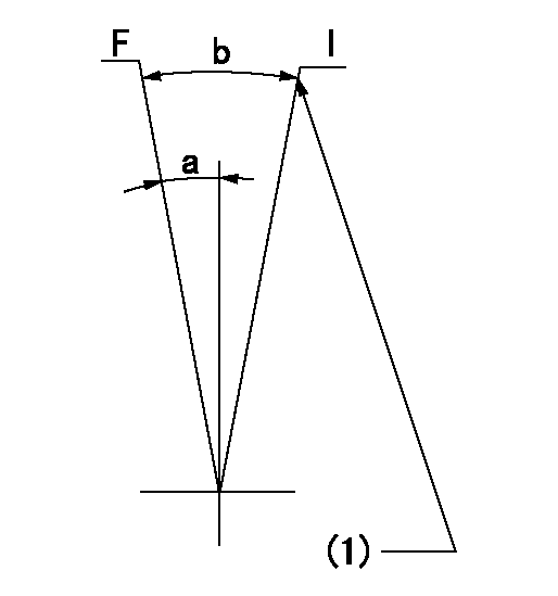
F:Full speed
I:Idle
(1)Stopper bolt setting
----------
----------
a=22deg+-5deg b=40deg+-5deg
----------
----------
a=22deg+-5deg b=40deg+-5deg
Stop lever angle
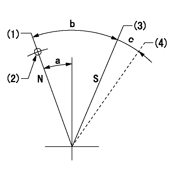
N:Pump normal
S:Stop the pump.
(1)Normal
(2)Use the hole at R = aa
(3)Contacts inner boss.
(4)Contacts outer boss.
----------
aa=23mm
----------
a=27deg+-5deg b=53deg+-5deg c=(11deg)
----------
aa=23mm
----------
a=27deg+-5deg b=53deg+-5deg c=(11deg)
0000001101
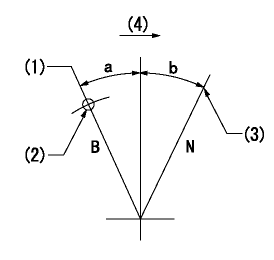
N:Normal
B:When boosted
(1)Rack position = aa at boost pressure 0.
(2)Use the hole at R = bb
(3)Stopper bolt setting
(4)Drive side
----------
aa=16+-0.1mm bb=30mm
----------
a=(20deg) b=(15deg)
----------
aa=16+-0.1mm bb=30mm
----------
a=(20deg) b=(15deg)
0000001501 Q ADJUSTMENT PIPING
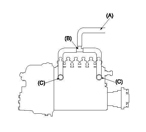
Tester fuel pipe A
(B) branch piping
Fuel inlet C
Piping at standard injection quantity adjustment
1. Because the pump gallery is divided into two, be careful of the fuel piping at adjustment.
----------
----------
----------
----------
Timing setting
(1)Pump vertical direction
(2)Coupling's key groove position at No 1 cylinder's beginning of injection
(3)B.T.D.C.: aa
(4)-
----------
aa=20deg
----------
a=(50deg)
----------
aa=20deg
----------
a=(50deg)
Have questions with 106682-3102?
Group cross 106682-3102 ZEXEL
Hino
106682-3102
9 400 617 525
220206152A
INJECTION-PUMP ASSEMBLY
P11B-TI
P11B-TI