Rating:
Information injection-pump assembly
BOSCH
9 400 611 902
9400611902
ZEXEL
106673-7870
1066737870
MITSUBISHI
ME152552
me152552
Service parts 106673-7870 INJECTION-PUMP ASSEMBLY:
1.
_
7.
COUPLING PLATE
8.
_
9.
_
11.
Nozzle and Holder
ME152351
12.
Open Pre:MPa(Kqf/cm2)
21.6{220}
15.
NOZZLE SET
Include in #1:
106673-7870
as INJECTION-PUMP ASSEMBLY
Cross reference number
BOSCH
9 400 611 902
9400611902
ZEXEL
106673-7870
1066737870
MITSUBISHI
ME152552
me152552
Zexel num
Bosch num
Firm num
Name
106673-7870
9 400 611 902
ME152552 MITSUBISHI
INJECTION-PUMP ASSEMBLY
6D24 K 14CA INJECTION PUMP ASSY PE6P,6PD PE
6D24 K 14CA INJECTION PUMP ASSY PE6P,6PD PE
Calibration Data:
Adjustment conditions
Test oil
1404 Test oil ISO4113 or {SAEJ967d}
1404 Test oil ISO4113 or {SAEJ967d}
Test oil temperature
degC
40
40
45
Nozzle and nozzle holder
105780-8140
Bosch type code
EF8511/9A
Nozzle
105780-0000
Bosch type code
DN12SD12T
Nozzle holder
105780-2080
Bosch type code
EF8511/9
Opening pressure
MPa
17.2
Opening pressure
kgf/cm2
175
Injection pipe
Outer diameter - inner diameter - length (mm) mm 8-3-600
Outer diameter - inner diameter - length (mm) mm 8-3-600
Overflow valve
131424-4620
Overflow valve opening pressure
kPa
255
221
289
Overflow valve opening pressure
kgf/cm2
2.6
2.25
2.95
Tester oil delivery pressure
kPa
157
157
157
Tester oil delivery pressure
kgf/cm2
1.6
1.6
1.6
Direction of rotation (viewed from drive side)
Right R
Right R
Injection timing adjustment
Direction of rotation (viewed from drive side)
Right R
Right R
Injection order
1-5-3-6-
2-4
Pre-stroke
mm
4.8
4.75
4.85
Beginning of injection position
Governor side NO.1
Governor side NO.1
Difference between angles 1
Cal 1-5 deg. 60 59.5 60.5
Cal 1-5 deg. 60 59.5 60.5
Difference between angles 2
Cal 1-3 deg. 120 119.5 120.5
Cal 1-3 deg. 120 119.5 120.5
Difference between angles 3
Cal 1-6 deg. 180 179.5 180.5
Cal 1-6 deg. 180 179.5 180.5
Difference between angles 4
Cyl.1-2 deg. 240 239.5 240.5
Cyl.1-2 deg. 240 239.5 240.5
Difference between angles 5
Cal 1-4 deg. 300 299.5 300.5
Cal 1-4 deg. 300 299.5 300.5
Injection quantity adjustment
Adjusting point
-
Rack position
7.4
Pump speed
r/min
700
700
700
Each cylinder's injection qty
mm3/st.
104.5
101.9
107.1
Basic
*
Fixing the rack
*
Standard for adjustment of the maximum variation between cylinders
*
Injection quantity adjustment_02
Adjusting point
C
Rack position
5.1+-0.5
Pump speed
r/min
225
225
225
Each cylinder's injection qty
mm3/st.
14.5
12.3
16.7
Fixing the rack
*
Standard for adjustment of the maximum variation between cylinders
*
Injection quantity adjustment_03
Adjusting point
A
Rack position
R1(7.4)
Pump speed
r/min
700
700
700
Average injection quantity
mm3/st.
104.5
103.5
105.5
Basic
*
Fixing the lever
*
Injection quantity adjustment_04
Adjusting point
B
Rack position
R1(7.4)
Pump speed
r/min
1100
1100
1100
Average injection quantity
mm3/st.
121.5
113.5
129.5
Fixing the lever
*
Injection quantity adjustment_05
Adjusting point
F
Rack position
-
Pump speed
r/min
100
100
100
Average injection quantity
mm3/st.
110
90
130
Fixing the lever
*
Remarks
After startup boost setting
After startup boost setting
Timer adjustment
Pump speed
r/min
(800)
Advance angle
deg.
0.5
Timer adjustment_02
Pump speed
r/min
1000
Advance angle
deg.
4
4
4
Remarks
Finish
Finish
Test data Ex:
Governor adjustment
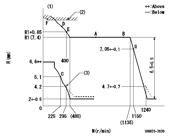
N:Pump speed
R:Rack position (mm)
(1)Tolerance for racks not indicated: +-0.05mm.
(2)Excess fuel setting for starting: SXL (N = N1)
(3)Damper spring setting
----------
SXL=9.3+0.2mm N1=225r/min
----------
----------
SXL=9.3+0.2mm N1=225r/min
----------
Speed control lever angle
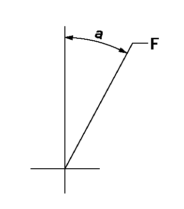
F:Full speed
----------
----------
a=27deg+-5deg
----------
----------
a=27deg+-5deg
0000000901
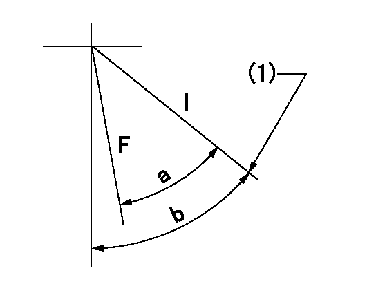
F:Full load
I:Idle
(1)Stopper bolt setting
----------
----------
a=20.5deg+-3deg b=21deg+-5deg
----------
----------
a=20.5deg+-3deg b=21deg+-5deg
Stop lever angle
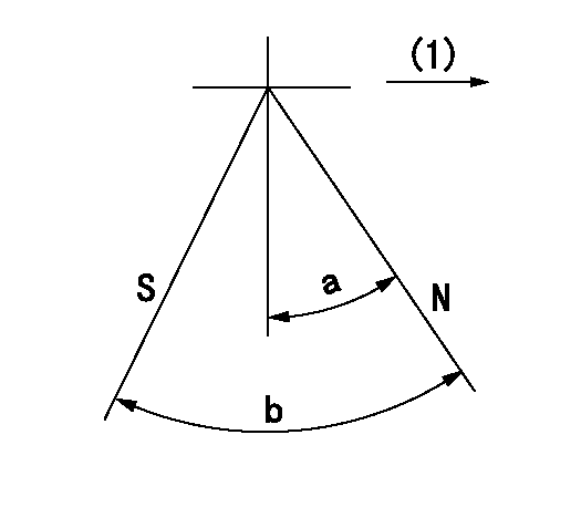
N:Pump normal
S:Stop the pump.
(1)Drive side
----------
----------
a=20deg+-5deg b=64deg+-5deg
----------
----------
a=20deg+-5deg b=64deg+-5deg
0000001501 ACS
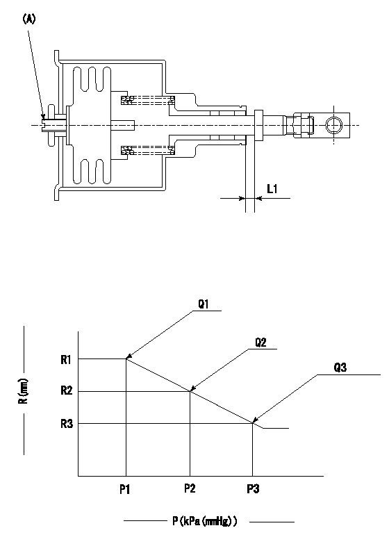
(A) Set screw
1. Adjustment of the aneroid compensator itself and the adjustment after mounting the governor
(1)Set the speed of the pump to N1 r/min and fix the control lever at the full set position.
(2)Screw in (A) to obtain the performance shown in the graph (to obtain L1).
----------
N1=700r/min L1=0.1~0.5mm
----------
R1=R1(7.4)mm R2=R1-0.45mm R3=R1-0.9mm P1=(88.8)kPa((666)mmHg) P2=(78.5)kPa((589)mmHg) P3=69.3+-0.7kPa(520+-5mmHg) Q1=104.5+-1cm3/1000st Q2=(94.5)cm3/1000st Q3=(84)cm3/1000st
----------
N1=700r/min L1=0.1~0.5mm
----------
R1=R1(7.4)mm R2=R1-0.45mm R3=R1-0.9mm P1=(88.8)kPa((666)mmHg) P2=(78.5)kPa((589)mmHg) P3=69.3+-0.7kPa(520+-5mmHg) Q1=104.5+-1cm3/1000st Q2=(94.5)cm3/1000st Q3=(84)cm3/1000st
Timing setting

(1)Pump vertical direction
(2)Coupling's key groove position at No 1 cylinder's beginning of injection
(3)B.T.D.C.: aa
(4)-
----------
aa=15deg
----------
a=(7deg)
----------
aa=15deg
----------
a=(7deg)
Have questions with 106673-7870?
Group cross 106673-7870 ZEXEL
Mitsubishi
Mitsubishi
106673-7870
9 400 611 902
ME152552
INJECTION-PUMP ASSEMBLY
6D24
6D24