
Rating:
Information injection-pump assembly
ZEXEL
106673-3010
1066733010
HINO
220009540A
220009540a
Cross reference number
ZEXEL
106673-3010
1066733010
HINO
220009540A
220009540a
Zexel num
Bosch num
Firm num
Name
Calibration Data:
Adjustment conditions
Test oil
1404 Test oil ISO4113 or {SAEJ967d}
1404 Test oil ISO4113 or {SAEJ967d}
Test oil temperature
degC
40
40
45
Nozzle and nozzle holder
105780-8140
Bosch type code
EF8511/9A
Nozzle
105780-0000
Bosch type code
DN12SD12T
Nozzle holder
105780-2080
Bosch type code
EF8511/9
Opening pressure
MPa
17.2
Opening pressure
kgf/cm2
175
Injection pipe
Outer diameter - inner diameter - length (mm) mm 8-3-600
Outer diameter - inner diameter - length (mm) mm 8-3-600
Overflow valve
134424-1420
Overflow valve opening pressure
kPa
162
147
177
Overflow valve opening pressure
kgf/cm2
1.65
1.5
1.8
Tester oil delivery pressure
kPa
157
157
157
Tester oil delivery pressure
kgf/cm2
1.6
1.6
1.6
Direction of rotation (viewed from drive side)
Left L
Left L
Injection timing adjustment
Direction of rotation (viewed from drive side)
Left L
Left L
Injection order
1-4-2-6-
3-5
Pre-stroke
mm
4.6
4.54
4.6
Beginning of injection position
Drive side NO.1
Drive side NO.1
Difference between angles 1
Cal 1-4 deg. 60 59.75 60.25
Cal 1-4 deg. 60 59.75 60.25
Difference between angles 2
Cyl.1-2 deg. 120 119.75 120.25
Cyl.1-2 deg. 120 119.75 120.25
Difference between angles 3
Cal 1-6 deg. 180 179.75 180.25
Cal 1-6 deg. 180 179.75 180.25
Difference between angles 4
Cal 1-3 deg. 240 239.75 240.25
Cal 1-3 deg. 240 239.75 240.25
Difference between angles 5
Cal 1-5 deg. 300 299.75 300.25
Cal 1-5 deg. 300 299.75 300.25
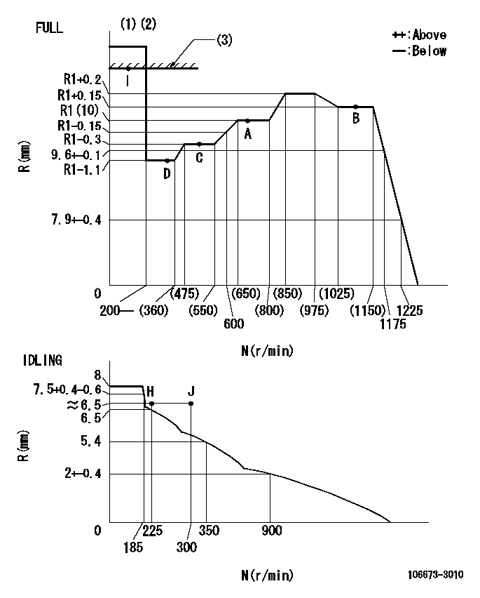
Injection quantity adjustment
Adjusting point
-
Rack position
10
Pump speed
r/min
700
700
700
Average injection quantity
mm3/st.
129
126
132
Max. variation between cylinders
%
0
-2
2
Basic
*
Fixing the rack
*
Standard for adjustment of the maximum variation between cylinders
*
Injection quantity adjustment_02
Adjusting point
H
Rack position
6.5+-0.5
Pump speed
r/min
225
225
225
Average injection quantity
mm3/st.
8.5
5.5
11.5
Max. variation between cylinders
%
0
-15
15
Fixing the rack
*
Standard for adjustment of the maximum variation between cylinders
*
Injection quantity adjustment_03
Adjusting point
A
Rack position
R1(10)
Pump speed
r/min
700
700
700
Average injection quantity
mm3/st.
129
127
131
Basic
*
Fixing the lever
*
Injection quantity adjustment_04
Adjusting point
B
Rack position
R1+0.15
Pump speed
r/min
1075
1075
1075
Average injection quantity
mm3/st.
135
129
141
Fixing the lever
*
Injection quantity adjustment_05
Adjusting point
C
Rack position
R1-0.3
Pump speed
r/min
500
500
500
Average injection quantity
mm3/st.
122
116
128
Fixing the lever
*
Injection quantity adjustment_06
Adjusting point
D
Rack position
R1-1.1
Pump speed
r/min
300
300
300
Average injection quantity
mm3/st.
75
69
81
Fixing the lever
*
Injection quantity adjustment_07
Adjusting point
I
Rack position
-
Pump speed
r/min
100
100
100
Average injection quantity
mm3/st.
165
165
185
Fixing the lever
*
Rack limit
*
Timer adjustment
Pump speed
r/min
695--
Advance angle
deg.
0
0
0
Load
1/4
Remarks
Start
Start
Timer adjustment_02
Pump speed
r/min
645
Advance angle
deg.
0.3
Load
1/4
Timer adjustment_03
Pump speed
r/min
(800)
Advance angle
deg.
1
0.7
1.3
Load
4/4
Remarks
Measure the actual speed.
Measure the actual speed.
Timer adjustment_04
Pump speed
r/min
860+50
Advance angle
deg.
1
0.7
1.3
Load
3/4
Timer adjustment_05
Pump speed
r/min
-
Advance angle
deg.
1
0.7
1.3
Load
4/4
Remarks
Measure the actual speed.
Measure the actual speed.
Timer adjustment_06
Pump speed
r/min
1075-50
Advance angle
deg.
5.5
5.2
5.8
Load
4/4
Remarks
Finish
Finish
Test data Ex:
Governor adjustment
N:Pump speed
R:Rack position (mm)
(1)Torque cam stamping: T1
(2)Tolerance for racks not indicated: +-0.05mm.
(3)RACK LIMIT
----------
T1=J28
----------
----------
T1=J28
----------
Speed control lever angle
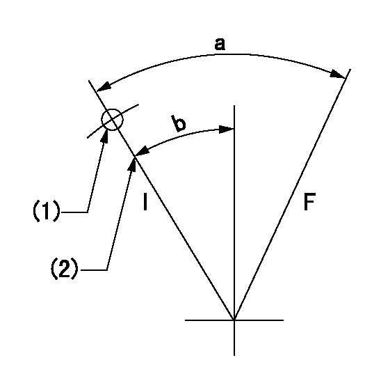
F:Full speed
I:Idle
(1)Use the hole at R = aa
(2)Stopper bolt set position 'H'
----------
aa=47mm
----------
a=40deg+-3deg b=18.5deg+-5deg
----------
aa=47mm
----------
a=40deg+-3deg b=18.5deg+-5deg
Stop lever angle
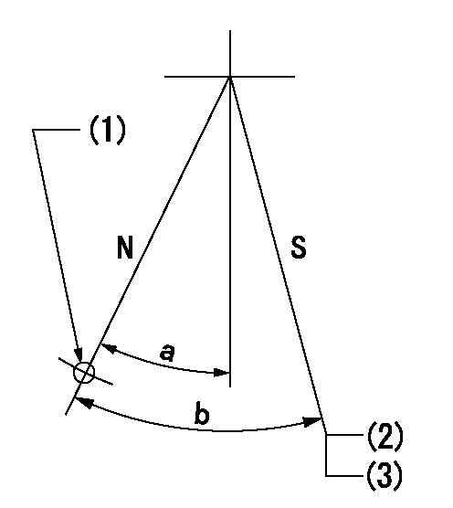
N:Pump normal
S:Stop the pump.
(1)Use the pin at R = aa
(2)With the speed lever in the full position at speed = bb, set the stop screw so that the rack position = cc (non-injection rack position).
(3)Next, at idle speed dd, confirm that there is no injection and measure the rack position. After adjustment, apply red paint.
----------
aa=40mm bb=1150r/min cc=4.2-0.5mm dd=225r/min
----------
a=31deg+-5deg b=(40deg)+-5deg
----------
aa=40mm bb=1150r/min cc=4.2-0.5mm dd=225r/min
----------
a=31deg+-5deg b=(40deg)+-5deg
0000001501 AIR CYLINDER
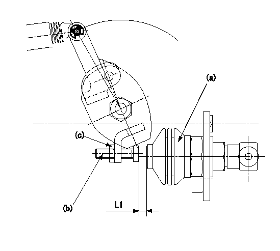
Adjustment of the air cylinder
1. Set the speed lever at the idling position.
2. Set the gap between the air cylinder (a) and the set bolt (b) to L1.
3. Set the speed at N1, apply positive pressure P1 to the air cylinder (a) and read the rack position.
4. Push set bolt (b) out and tighten nut (c) at N1 when the rack position is R1.
5. Apply positive pressure several times and confirm that the lever returns to the idle position at positive pressure P2.
6. Confirm that the rack position is R1 at positive pressure P1.
----------
L1=(8)mm R1=6.5+-0.1mm N1=335r/min P1=392+98kPa(4+1kgf/cm2) P2=0kPa(0kgf/cm2)
----------
----------
L1=(8)mm R1=6.5+-0.1mm N1=335r/min P1=392+98kPa(4+1kgf/cm2) P2=0kPa(0kgf/cm2)
----------
Timing setting

(1)Pump vertical direction
(2)Coupling's key groove position at No 1 cylinder's beginning of injection
(3)-
(4)-
----------
----------
a=(4deg)
----------
----------
a=(4deg)