
Rating:
Information injection-pump assembly
BOSCH
9 400 616 894
9400616894
ZEXEL
106671-5990
1066715990
NISSAN-DIESEL
1671496519
1671496519
Cross reference number
BOSCH
9 400 616 894
9400616894
ZEXEL
106671-5990
1066715990
NISSAN-DIESEL
1671496519
1671496519
Zexel num
Bosch num
Firm num
Name
106671-5990
9 400 616 894
1671496519 NISSAN-DIESEL
INJECTION-PUMP ASSEMBLY
PE6TE K
PE6TE K
Calibration Data:
Adjustment conditions
Test oil
1404 Test oil ISO4113 or {SAEJ967d}
1404 Test oil ISO4113 or {SAEJ967d}
Test oil temperature
degC
40
40
45
Nozzle and nozzle holder
105780-8140
Bosch type code
EF8511/9A
Nozzle
105780-0000
Bosch type code
DN12SD12T
Nozzle holder
105780-2080
Bosch type code
EF8511/9
Opening pressure
MPa
17.2
Opening pressure
kgf/cm2
175
Injection pipe
Outer diameter - inner diameter - length (mm) mm 8-3-600
Outer diameter - inner diameter - length (mm) mm 8-3-600
Overflow valve
132424-0620
Overflow valve opening pressure
kPa
157
123
191
Overflow valve opening pressure
kgf/cm2
1.6
1.25
1.95
Tester oil delivery pressure
kPa
157
157
157
Tester oil delivery pressure
kgf/cm2
1.6
1.6
1.6
Direction of rotation (viewed from drive side)
Right R
Right R
Injection timing adjustment
Direction of rotation (viewed from drive side)
Right R
Right R
Injection order
1-4-2-6-
3-5
Pre-stroke
mm
3.65
3.6
3.7
Beginning of injection position
Drive side NO.1
Drive side NO.1
Difference between angles 1
Cal 1-4 deg. 60 59.5 60.5
Cal 1-4 deg. 60 59.5 60.5
Difference between angles 2
Cyl.1-2 deg. 120 119.5 120.5
Cyl.1-2 deg. 120 119.5 120.5
Difference between angles 3
Cal 1-6 deg. 180 179.5 180.5
Cal 1-6 deg. 180 179.5 180.5
Difference between angles 4
Cal 1-3 deg. 240 239.5 240.5
Cal 1-3 deg. 240 239.5 240.5
Difference between angles 5
Cal 1-5 deg. 300 299.5 300.5
Cal 1-5 deg. 300 299.5 300.5
Injection quantity adjustment
Adjusting point
A
Rack position
10.9
Pump speed
r/min
650
650
650
Average injection quantity
mm3/st.
149
147
151
Max. variation between cylinders
%
0
-4
4
Basic
*
Fixing the lever
*
Boost pressure
kPa
65.3
65.3
Boost pressure
mmHg
490
490
Solenoid boost comp. OFF
*
Injection quantity adjustment_02
Adjusting point
C
Rack position
6.7+-0.5
Pump speed
r/min
270
270
270
Average injection quantity
mm3/st.
15.5
14.5
16.5
Max. variation between cylinders
%
0
-10
10
Fixing the rack
*
Boost pressure
kPa
0
0
0
Boost pressure
mmHg
0
0
0
Solenoid boost comp. OFF
*
Injection quantity adjustment_03
Adjusting point
D
Rack position
9.7
Pump speed
r/min
400
400
400
Average injection quantity
mm3/st.
109
106
112
Fixing the lever
*
Boost pressure
kPa
0
0
0
Boost pressure
mmHg
0
0
0
Solenoid boost comp. OFF
*
Boost compensator adjustment
Pump speed
r/min
400
400
400
Rack position
9.7
Boost pressure
kPa
18.7
17.4
20
Boost pressure
mmHg
140
130
150
Boost compensator adjustment_02
Pump speed
r/min
400
400
400
Rack position
10.9
Boost pressure
kPa
38.7
34.7
42.7
Boost pressure
mmHg
290
260
320
Boost compensator adjustment_03
Pump speed
r/min
400
400
400
Rack position
(11.5)
Boost pressure
kPa
52
52
52
Boost pressure
mmHg
390
390
390
Timer adjustment
Pump speed
r/min
-
Advance angle
deg.
0.5
Remarks
Measure the actual speed.
Measure the actual speed.
Timer adjustment_02
Pump speed
r/min
-
Advance angle
deg.
1
0.5
1.5
Remarks
Measure the actual speed, stop
Measure the actual speed, stop
Test data Ex:
Governor adjustment
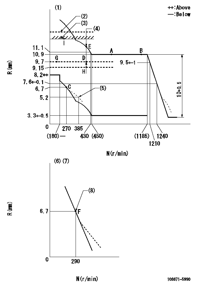
N:Pump speed
R:Rack position (mm)
(1)Tolerance for racks not indicated: +-0.05mm.
(2)Solenoid boost compensator OFF: SBL
(3)Rack limit using the stop lever: R1
(4)Boost compensator stroke: BCL
(5)Damper spring setting
(6)Variable speed specification: idling adjustment
(7)Fix the lever at the full-load position at delivery.
(8)Main spring setting
----------
SBL=(13.15)mm R1=12.9+0.2mm BCL=(1.8)mm
----------
----------
SBL=(13.15)mm R1=12.9+0.2mm BCL=(1.8)mm
----------
Speed control lever angle
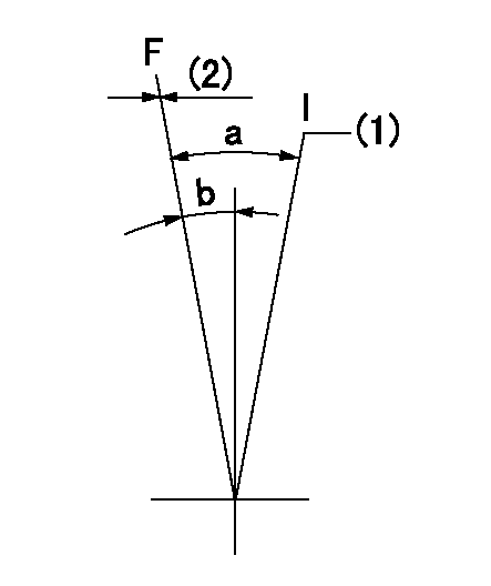
F:Full speed
I:Idle
(1)Pump speed = aa
(2)Set the stopper bolt (fixed at full-load position at delivery.)
----------
aa=290r/min
----------
a=(16.5deg)+-5deg b=(8.5deg)+-5deg
----------
aa=290r/min
----------
a=(16.5deg)+-5deg b=(8.5deg)+-5deg
0000000901
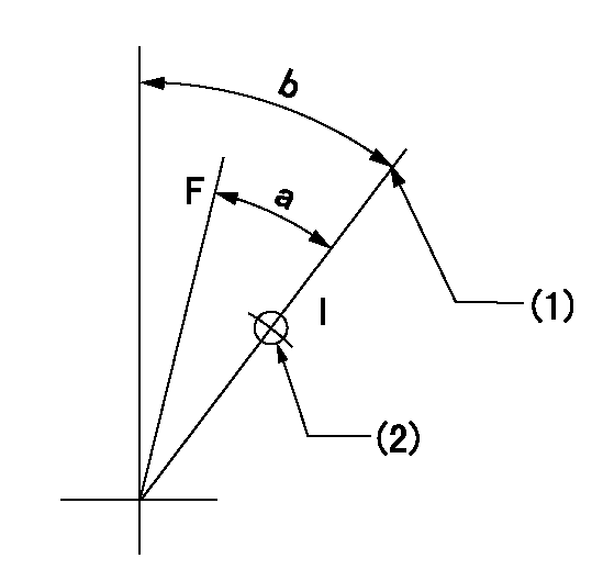
F:Full load
I:Idle
(1)Stopper bolt setting
(2)Use the hole at R = aa
----------
aa=42mm
----------
a=28deg+-3deg b=45deg+-5deg
----------
aa=42mm
----------
a=28deg+-3deg b=45deg+-5deg
Stop lever angle
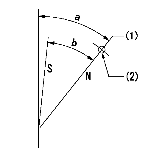
N:Pump normal
S:Stop the pump.
(1)Rack position aa (pump speed bb r/min )
(2)Use the pin above R = cc
----------
aa=12.9+0.2mm bb=250r/min cc=40mm
----------
a=(42.5deg)+-5deg b=(41.5deg)+-5deg
----------
aa=12.9+0.2mm bb=250r/min cc=40mm
----------
a=(42.5deg)+-5deg b=(41.5deg)+-5deg
0000001501 BCS
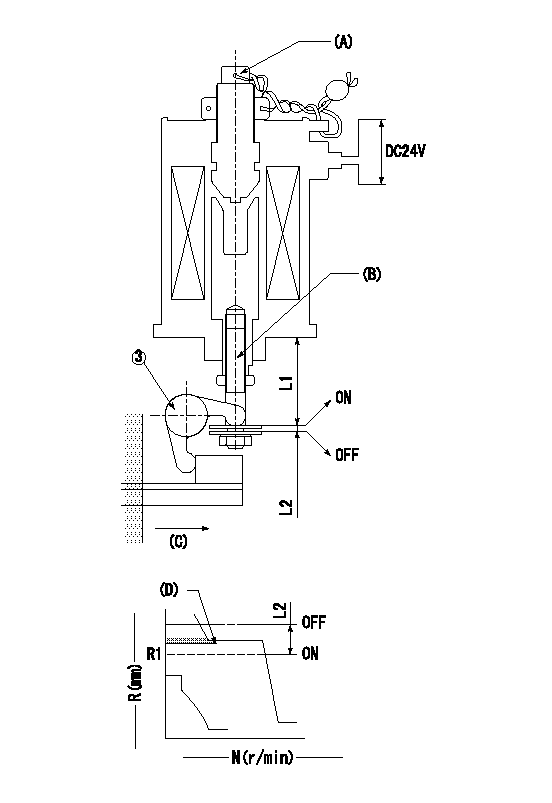
(A) Screw for precise adjustment
(B) Pre-adjustment screw
(C) Control rack, rack decrease direction
(D) Rack limit
1. Solenoid boost compensator adjustment
(1)Supply DC: V1 to the solenoid terminals and confirm solenoid operation.
(2)With the solenoid ON, calculate L1 from the value of R1. [L1 = La - (10.5 - R1) +-0.2]
(3)Adjust (B) to obtain L1.
(4)Assemble the solenoid to the governor.
(5)With the solenoid ON, readjust (B) so that R1 is within the allowance a.
(6)With the solenoid OFF, perform all governor adjustments except rack limit adjustment.
(7)Set the pump speed at N1 and turn the solenoid ON.
(8)Adjust (A) so that R1 is within the allowance range a.
(9)Set the pump speed at N1 and fix the load lever in the full position
(10)Turn the solenoid switch ON and OFF several times and confirm that the difference in rack positions is within L2.
(11)Set the rack limit.
(12)Stamp the solenoid valve.
----------
V1=24V N1=400r/min N2=0r/min R1=9.15mm a=+-0.5mm La=28mm L1=26.65+-0.2mm L2=3.5~5mm
----------
----------
V1=24V N1=400r/min N2=0r/min R1=9.15mm a=+-0.5mm La=28mm L1=26.65+-0.2mm L2=3.5~5mm
----------
0000001601 TAMPER PROOF
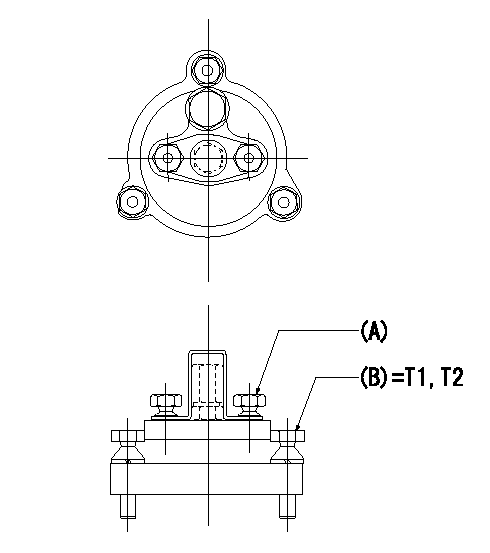
Tamperproofing-equipped boost compensator cover installation procedure
(A): After adjusting the boost compensator, assemble then tighten the bolts to remove the heads.
(B): Specified torque
(1)Before adjusting the governor and the boost compensator, tighten the screw to the specified torque.
(Tightening torque T = T1 maximum)
(2)After adjusting the governor and the boost compensator, tighten to the specified torque to break off the bolt heads.
(Tightening torque T = T2)
----------
T1=2.5N-m(0.25kgf-m) T2=2.9~4.4N-m(0.3~0.45kgf-m)
----------
----------
T1=2.5N-m(0.25kgf-m) T2=2.9~4.4N-m(0.3~0.45kgf-m)
----------
Timing setting
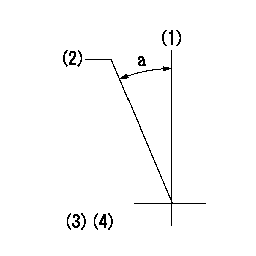
(1)Pump vertical direction
(2)Coupling's key groove position at No 1 cylinder's beginning of injection
(3)-
(4)-
----------
----------
a=(30deg)
----------
----------
a=(30deg)
Have questions with 106671-5990?
Group cross 106671-5990 ZEXEL
Nissan-Diesel
106671-5990
9 400 616 894
1671496519
INJECTION-PUMP ASSEMBLY
PE6TE
PE6TE