
Rating:
Information injection-pump assembly
ZEXEL
106671-5220
1066715220
Cross reference number
ZEXEL
106671-5220
1066715220
Zexel num
Bosch num
Firm num
Name
106671-5220
INJECTION-PUMP ASSEMBLY
Calibration Data:
Adjustment conditions
Test oil
1404 Test oil ISO4113 or {SAEJ967d}
1404 Test oil ISO4113 or {SAEJ967d}
Test oil temperature
degC
40
40
45
Nozzle and nozzle holder
105780-8140
Bosch type code
EF8511/9A
Nozzle
105780-0000
Bosch type code
DN12SD12T
Nozzle holder
105780-2080
Bosch type code
EF8511/9
Opening pressure
MPa
17.2
Opening pressure
kgf/cm2
175
Injection pipe
Outer diameter - inner diameter - length (mm) mm 8-3-600
Outer diameter - inner diameter - length (mm) mm 8-3-600
Overflow valve
132424-0620
Overflow valve opening pressure
kPa
157
123
191
Overflow valve opening pressure
kgf/cm2
1.6
1.25
1.95
Tester oil delivery pressure
kPa
157
157
157
Tester oil delivery pressure
kgf/cm2
1.6
1.6
1.6
Direction of rotation (viewed from drive side)
Right R
Right R
Injection timing adjustment
Direction of rotation (viewed from drive side)
Right R
Right R
Injection order
1-4-2-6-
3-5
Pre-stroke
mm
3.65
3.6
3.7
Beginning of injection position
Drive side NO.1
Drive side NO.1
Difference between angles 1
Cal 1-4 deg. 60 59.5 60.5
Cal 1-4 deg. 60 59.5 60.5
Difference between angles 2
Cyl.1-2 deg. 120 119.5 120.5
Cyl.1-2 deg. 120 119.5 120.5
Difference between angles 3
Cal 1-6 deg. 180 179.5 180.5
Cal 1-6 deg. 180 179.5 180.5
Difference between angles 4
Cal 1-3 deg. 240 239.5 240.5
Cal 1-3 deg. 240 239.5 240.5
Difference between angles 5
Cal 1-5 deg. 300 299.5 300.5
Cal 1-5 deg. 300 299.5 300.5
Injection quantity adjustment
Adjusting point
A
Rack position
11.6
Pump speed
r/min
600
600
600
Average injection quantity
mm3/st.
154.8
152.8
156.8
Max. variation between cylinders
%
0
-4
4
Basic
*
Fixing the lever
*
Boost pressure
kPa
29.3
29.3
Boost pressure
mmHg
220
220
Injection quantity adjustment_02
Adjusting point
C
Rack position
10.4
Pump speed
r/min
300
300
300
Average injection quantity
mm3/st.
117.4
115.4
119.4
Fixing the lever
*
Boost pressure
kPa
0
0
0
Boost pressure
mmHg
0
0
0
Injection quantity adjustment_03
Adjusting point
E
Rack position
7.8+-0.5
Pump speed
r/min
225
225
225
Average injection quantity
mm3/st.
14.3
13.3
15.3
Max. variation between cylinders
%
0
-10
10
Fixing the rack
*
Boost pressure
kPa
0
0
0
Boost pressure
mmHg
0
0
0
Boost compensator adjustment
Pump speed
r/min
300
300
300
Rack position
10.4
Boost pressure
kPa
4
2.7
5.3
Boost pressure
mmHg
30
20
40
Boost compensator adjustment_02
Pump speed
r/min
300
300
300
Rack position
12.3+0.2
Boost pressure
kPa
16
16
16
Boost pressure
mmHg
120
120
120
Timer adjustment
Pump speed
r/min
1200--
Advance angle
deg.
0
0
0
Remarks
Start
Start
Timer adjustment_02
Pump speed
r/min
1150
Advance angle
deg.
0.5
Timer adjustment_03
Pump speed
r/min
-
Advance angle
deg.
2
2
2
Remarks
Measure the actual speed, stop
Measure the actual speed, stop
Test data Ex:
Governor adjustment
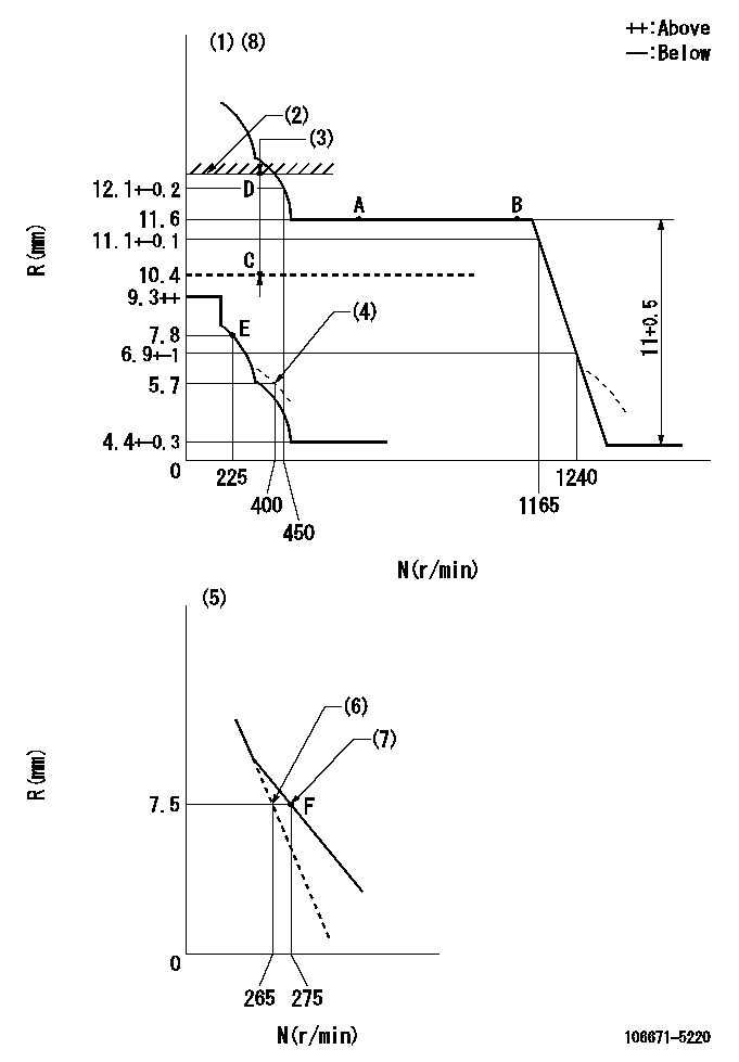
N:Pump speed
R:Rack position (mm)
(1)Tolerance for racks not indicated: +-0.05mm.
(2)Rack limit using the stop lever: R1
(3)Boost compensator stroke: BCL
(4)Damper spring setting
(5)Variable speed specification: idling adjustment
(6)Main spring setting
(7)Set idle sub-spring
(8)Perform governor adjustment at an ambient temperature of at least 15 deg C (boost compensator start spring is shape memory alloy).
----------
R1=12.3+0.2mm BCL=2+-0.1mm
----------
----------
R1=12.3+0.2mm BCL=2+-0.1mm
----------
Speed control lever angle
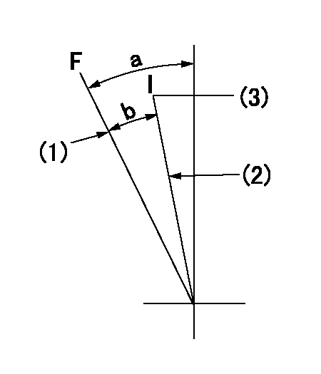
F:Full speed
I:Idle
(1)Stopper bolt setting
(2)Stopper bolt setting
(3)Set the pump speed at aa
----------
aa=275r/min
----------
a=23deg+-5deg b=15deg+-5deg
----------
aa=275r/min
----------
a=23deg+-5deg b=15deg+-5deg
0000000901
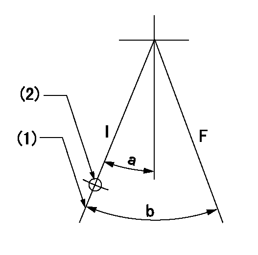
F:Full load
I:Idle
(1)Stopper bolt setting
(2)At center of threaded hole above R = aa
----------
aa=17mm
----------
a=15deg+-5deg b=27deg+-3deg
----------
aa=17mm
----------
a=15deg+-5deg b=27deg+-3deg
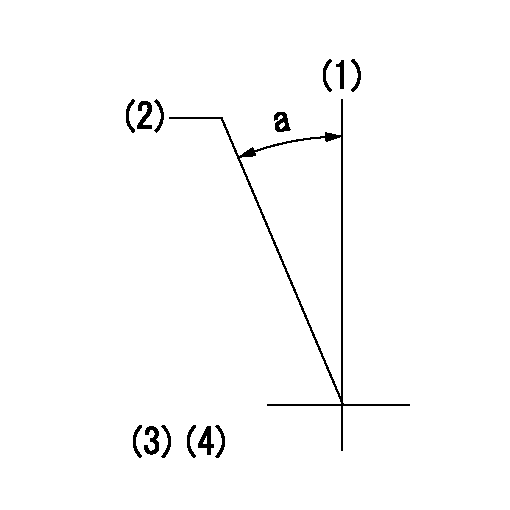
Stop lever angle
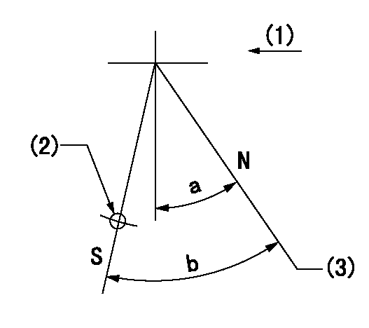
N:Pump normal
S:Stop the pump.
(1)Drive side
(2)Use the hole at R = aa
(3)Rack position bb
----------
aa=50mm bb=12.3+0.2mm
----------
a=30deg+-5deg b=32deg+-5deg
----------
aa=50mm bb=12.3+0.2mm
----------
a=30deg+-5deg b=32deg+-5deg
0000001501 ACS
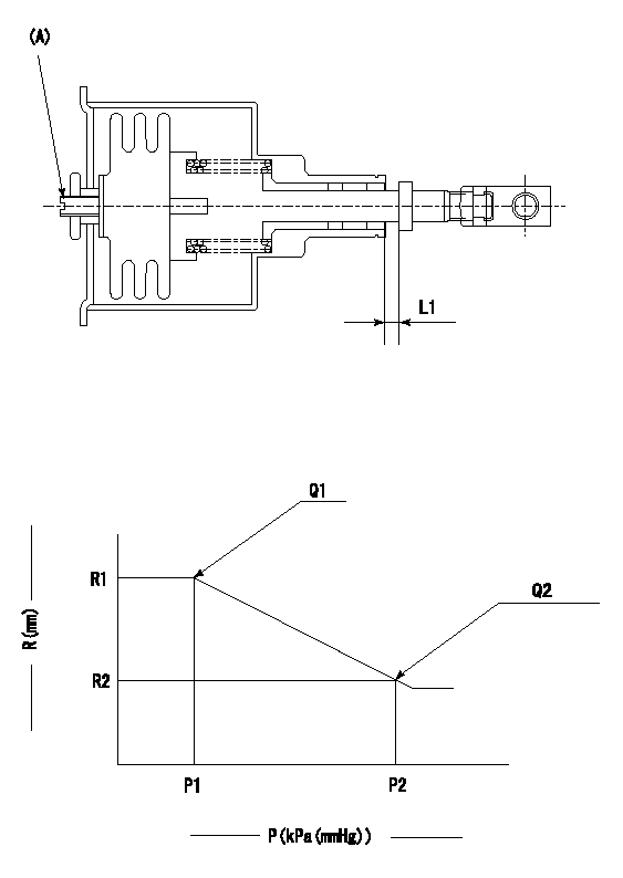
(A) Set screw
1. Aneroid compensator unit adjustment
Screw in (A) to obtain L1.
2. Adjustment following governor installation
(1)Set the speed of the pump to N1 r/min and fix the control lever at the full set position.
(2)Screw in the aneroid compensator to obtain the performance shown in the graph above.
----------
N1=1100r/min L1=0.1~0.5mm
----------
R1=11.6mm R2=(9.0)mm P1=90.6+-2.7kPa(680+-20mmHg) P2=57.7+-0.7kPa(433+-5mmHg) Q1=(152.6)+-4cm3/1000st Q2=90.2+-2cm3/1000st
----------
N1=1100r/min L1=0.1~0.5mm
----------
R1=11.6mm R2=(9.0)mm P1=90.6+-2.7kPa(680+-20mmHg) P2=57.7+-0.7kPa(433+-5mmHg) Q1=(152.6)+-4cm3/1000st Q2=90.2+-2cm3/1000st
Timing setting
(1)Pump vertical direction
(2)Coupling's key groove position at No 1 cylinder's beginning of injection
(3)-
(4)-
----------
----------
a=(30deg)
----------
----------
a=(30deg)
Have questions with 106671-5220?
Group cross 106671-5220 ZEXEL
Nissan-Diesel
Nissan-Diesel
106671-5220
INJECTION-PUMP ASSEMBLY