
Rating:
Information injection-pump assembly
ZEXEL
106671-1970
1066711970
ISUZU
1156029730
1156029730
Service parts 106671-1970 INJECTION-PUMP ASSEMBLY:
1.
_
7.
COUPLING PLATE
8.
_
9.
_
11.
Nozzle and Holder
1-15300-303-2
12.
Open Pre:MPa(Kqf/cm2)
19.6{200}
15.
NOZZLE SET
Include in #1:
106671-1970
as INJECTION-PUMP ASSEMBLY
Cross reference number
ZEXEL
106671-1970
1066711970
ISUZU
1156029730
1156029730
Zexel num
Bosch num
Firm num
Name
106671-1970
1156029730 ISUZU
INJECTION-PUMP ASSEMBLY
6RB1-MTC * K 14CA PE6P,6PD PE
6RB1-MTC * K 14CA PE6P,6PD PE
Calibration Data:
Adjustment conditions
Test oil
1404 Test oil ISO4113 or {SAEJ967d}
1404 Test oil ISO4113 or {SAEJ967d}
Test oil temperature
degC
40
40
45
Nozzle and nozzle holder
105780-8130
Bosch type code
EFEP215A
Nozzle
105780-0050
Bosch type code
DN6TD119NP1T
Nozzle holder
105780-2090
Bosch type code
EFEP215
Opening pressure
MPa
17.2
Opening pressure
kgf/cm2
175
Injection pipe
Outer diameter - inner diameter - length (mm) mm 8-3-600
Outer diameter - inner diameter - length (mm) mm 8-3-600
Overflow valve
134424-3920
Overflow valve opening pressure
kPa
127
107
147
Overflow valve opening pressure
kgf/cm2
1.3
1.1
1.5
Tester oil delivery pressure
kPa
157
157
157
Tester oil delivery pressure
kgf/cm2
1.6
1.6
1.6
Direction of rotation (viewed from drive side)
Right R
Right R
Injection timing adjustment
Direction of rotation (viewed from drive side)
Right R
Right R
Injection order
1-4-2-6-
3-5
Pre-stroke
mm
4.2
4.15
4.25
Beginning of injection position
Drive side NO.1
Drive side NO.1
Difference between angles 1
Cal 1-4 deg. 60 59.5 60.5
Cal 1-4 deg. 60 59.5 60.5
Difference between angles 2
Cyl.1-2 deg. 120 119.5 120.5
Cyl.1-2 deg. 120 119.5 120.5
Difference between angles 3
Cal 1-6 deg. 180 179.5 180.5
Cal 1-6 deg. 180 179.5 180.5
Difference between angles 4
Cal 1-3 deg. 240 239.5 240.5
Cal 1-3 deg. 240 239.5 240.5
Difference between angles 5
Cal 1-5 deg. 300 299.5 300.5
Cal 1-5 deg. 300 299.5 300.5
Injection quantity adjustment
Adjusting point
A
Rack position
11.5
Pump speed
r/min
1000
1000
1000
Average injection quantity
mm3/st.
412
409
415
Max. variation between cylinders
%
0
-3
3
Basic
*
Fixing the lever
*
Boost pressure
kPa
140
140
Boost pressure
mmHg
1050
1050
Injection quantity adjustment_02
Adjusting point
-
Rack position
4.5
Pump speed
r/min
305
305
305
Average injection quantity
mm3/st.
15.5
12.3
18.7
Max. variation between cylinders
%
0
-13
13
Fixing the rack
*
Boost pressure
kPa
0
0
0
Boost pressure
mmHg
0
0
0
Remarks
Adjust only variation between cylinders; adjust governor according to governor specifications.
Adjust only variation between cylinders; adjust governor according to governor specifications.
Injection quantity adjustment_03
Adjusting point
C
Rack position
7.9
Pump speed
r/min
500
500
500
Average injection quantity
mm3/st.
207
201
213
Fixing the lever
*
Boost pressure
kPa
0
0
0
Boost pressure
mmHg
0
0
0
Boost compensator adjustment
Pump speed
r/min
500
500
500
Rack position
7.9
Boost pressure
kPa
22
20.7
23.3
Boost pressure
mmHg
165
155
175
Boost compensator adjustment_02
Pump speed
r/min
500
500
500
Rack position
(11.5)
Boost pressure
kPa
126.6
126.6
126.6
Boost pressure
mmHg
950
950
950
Timer adjustment
Pump speed
r/min
1050++
Advance angle
deg.
0
0
0
Remarks
Do not advance until starting N = 1050.
Do not advance until starting N = 1050.
Timer adjustment_02
Pump speed
r/min
-
Advance angle
deg.
1
1
1
Remarks
Measure the actual speed, stop
Measure the actual speed, stop
Test data Ex:
Governor adjustment

N:Pump speed
R:Rack position (mm)
(1)Lever ratio: RT
(2)Target shim dimension: TH
(3)Tolerance for racks not indicated: +-0.05mm.
(4)Boost compensator excessive fuel lever setting: L1 (at boost pressure 0)
(5)Boost compensator stroke: BCL
(6)Set idle sub-spring
(7)Main spring setting
----------
RT=1 TH=2.5mm L1=12.5+-0.1mm BCL=(3.6)+-0.1mm
----------
----------
RT=1 TH=2.5mm L1=12.5+-0.1mm BCL=(3.6)+-0.1mm
----------
Speed control lever angle
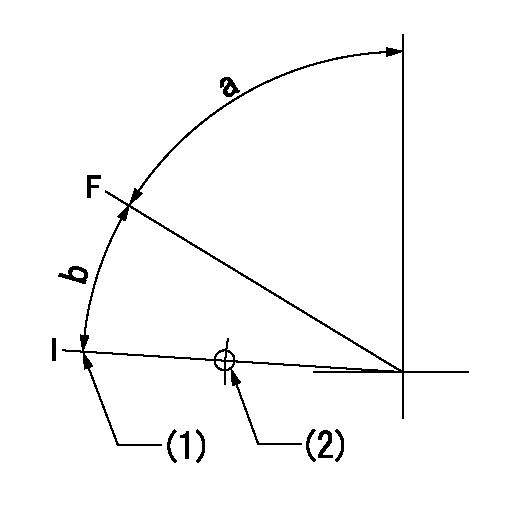
F:Full speed
I:Idle
(1)Stopper bolt setting
(2)Use the hole at R = aa
----------
aa=85.1mm
----------
a=68deg+-5deg b=14deg+-5deg
----------
aa=85.1mm
----------
a=68deg+-5deg b=14deg+-5deg
0000000901
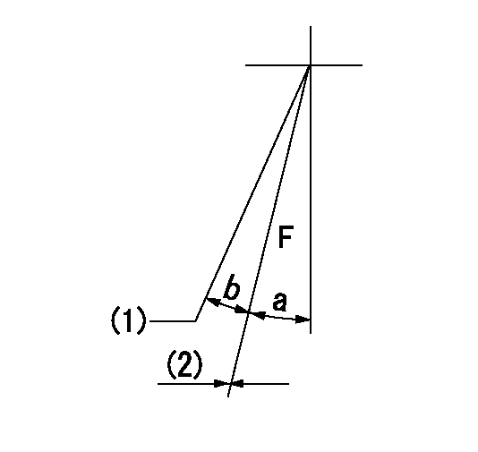
F:Full load
(1)Set the tamper proofing.
(2)Fix using the stopper bolt (seal at shipping).
----------
----------
a=16deg+-5deg b=(2.5deg)
----------
----------
a=16deg+-5deg b=(2.5deg)
Stop lever angle
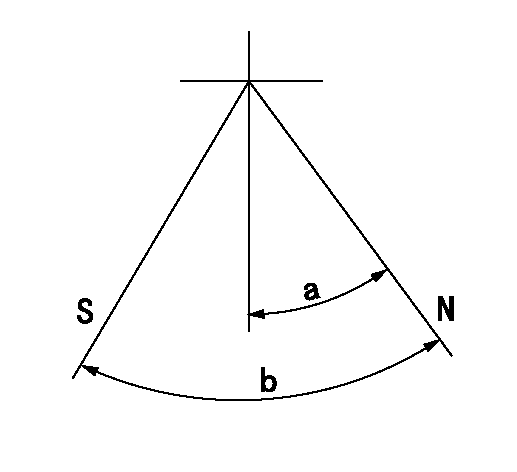
N:Pump normal
S:Stop the pump.
----------
----------
a=32deg+-5deg b=64deg+-5deg
----------
----------
a=32deg+-5deg b=64deg+-5deg
0000001101
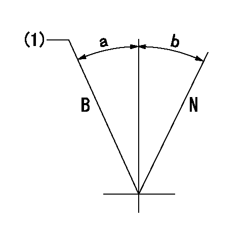
N:Normal
B:When boosted
(1)Rack position = aa at boost pressure 0.
----------
aa=12.5+-0.1mm
----------
a=(15deg) b=(15deg)
----------
aa=12.5+-0.1mm
----------
a=(15deg) b=(15deg)
0000001501 TAMPER PROOF
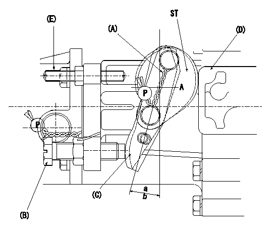
(A): sealing wire
(B): full load stopper bolt
(C): load lever
(D): governor cover boss
(E): tamper lever installation bolt
ST:Sealing
a, b: load lever angle
1. Method for setting tamperproof proofing
(1)After completing governor adjustment, install lever marked A when the load lever (C)'s angle is equal to or greater than a but less than b, and lever marked B when angle is equal to or greater than c but equal to or less than d (as shown in figure).
Sealing A: PN1
Sealing B: PN2
(2)At R1 and N1 loosen bolt B until the lever installed in (1) contacts the governor cover boss.
(3)Confirm that the rack position at this time is R = R2 or less.
(4)After this, readjust the full rack position using the load lever C.
(5)Seal bolt E.
----------
a=11deg b=16deg c=16deg d=21deg PN1=154386-3300 PN2=154386-3400 R1=L R2=(2)mm N1=1400r/min
----------
----------
a=11deg b=16deg c=16deg d=21deg PN1=154386-3300 PN2=154386-3400 R1=L R2=(2)mm N1=1400r/min
----------
Timing setting

(1)Pump vertical direction
(2)Position of timer's threaded hole at No 1 cylinder's beginning of injection
(3)B.T.D.C.: aa
(4)-
----------
aa=15deg
----------
a=(70deg)
----------
aa=15deg
----------
a=(70deg)
Have questions with 106671-1970?
Group cross 106671-1970 ZEXEL
Isuzu
Isuzu
Isuzu
Isuzu
106671-1970
1156029730
INJECTION-PUMP ASSEMBLY
6RB1-MTC
6RB1-MTC