
Rating:
Information injection-pump assembly
ZEXEL
104769-2000
1047692000
Cross reference number
ZEXEL
104769-2000
1047692000
Zexel num
Bosch num
Firm num
Name
104769-2000
INJECTION-PUMP ASSEMBLY
Calibration Data:
Adjustment conditions
Test oil
1404 Test oil ISO4113orSAEJ967d
1404 Test oil ISO4113orSAEJ967d
Test oil temperature
degC
45
45
50
Nozzle
105000-2010
Bosch type code
NP-DN12SD12TT
Nozzle holder
105780-2080
Opening pressure
MPa
14.7
14.7
15.19
Opening pressure
kgf/cm2
150
150
155
Injection pipe
Inside diameter - outside diameter - length (mm) mm 2-6-840
Inside diameter - outside diameter - length (mm) mm 2-6-840
Transfer pump pressure
kPa
20
20
20
Transfer pump pressure
kgf/cm2
0.2
0.2
0.2
Direction of rotation (viewed from drive side)
Right R
Right R
(Solenoid timer adjustment condition)
ON
Injection timing adjustment
Pump speed
r/min
1200
1200
1200
Average injection quantity
mm3/st.
31.2
30.7
31.7
Difference in delivery
mm3/st.
2.5
Basic
*
Injection timing adjustment_02
Pump speed
r/min
2700
2700
2700
Average injection quantity
mm3/st.
12.6
9.1
16.1
Injection timing adjustment_03
Pump speed
r/min
2300
2300
2300
Average injection quantity
mm3/st.
31
28
34
Injection timing adjustment_04
Pump speed
r/min
1200
1200
1200
Average injection quantity
mm3/st.
31.2
30.2
32.2
Injection timing adjustment_05
Pump speed
r/min
600
600
600
Average injection quantity
mm3/st.
29.5
27.5
31.5
Injection quantity adjustment
Pump speed
r/min
2700
2700
2700
Average injection quantity
mm3/st.
12.6
9.6
15.6
Basic
*
Injection quantity adjustment_02
Pump speed
r/min
2800
2800
2800
Average injection quantity
mm3/st.
5
Governor adjustment
Pump speed
r/min
350
350
350
Average injection quantity
mm3/st.
7.8
6.3
9.3
Difference in delivery
mm3/st.
3
Basic
*
Governor adjustment_02
Pump speed
r/min
350
350
350
Average injection quantity
mm3/st.
7.8
5.8
9.8
Governor adjustment_03
Pump speed
r/min
500
500
500
Average injection quantity
mm3/st.
4
Timer adjustment
Pump speed
r/min
100
100
100
Average injection quantity
mm3/st.
44.8
40.8
48.8
Basic
*
Speed control lever angle
Pump speed
r/min
350
350
350
Average injection quantity
mm3/st.
0
0
0
Remarks
Magnet OFF
Magnet OFF
0000000901
Pump speed
r/min
1200
1200
1200
Overflow quantity with S/T ON
cm3/min
402
270
534
Stop lever angle
Pump speed
r/min
1200
1200
1200
Pressure with S/T ON
kPa
431.5
402
461
Pressure with S/T ON
kgf/cm2
4.4
4.1
4.7
Basic
*
Stop lever angle_02
Pump speed
r/min
600
600
600
Pressure with S/T ON
kPa
294
255
333
Pressure with S/T ON
kgf/cm2
3
2.6
3.4
Stop lever angle_03
Pump speed
r/min
1200
1200
1200
Pressure with S/T ON
kPa
431.5
392
471
Pressure with S/T ON
kgf/cm2
4.4
4
4.8
Pressure with S/T OFF
kPa
343
304
382
Pressure with S/T OFF
kgf/cm2
3.5
3.1
3.9
Stop lever angle_04
Pump speed
r/min
2300
2300
2300
Pressure with S/T ON
kPa
696
657
735
Pressure with S/T ON
kgf/cm2
7.1
6.7
7.5
0000001101
Pump speed
r/min
1200
1200
1200
Timer stroke with S/T ON
mm
4.3
4
4.6
Basic
*
_02
Pump speed
r/min
800
800
800
Timer stroke with S/T ON
mm
2.4
1.8
3
_03
Pump speed
r/min
1200
1200
1200
Timer stroke with S/T ON
mm
4.3
3.9
4.7
Timer stroke with S/T OFF
mm
3
2.6
3.4
_04
Pump speed
r/min
2300
2300
2300
Timer stroke with S/T ON
mm
8.15
7.7
8.6
0000001201
Max. applied voltage
V
8
8
8
Test voltage
V
13
12
14
0000001501
Pump speed
r/min
1200
1200
1200
Atmospheric pressure difference
kPa
-18.7
-18.7
-18.7
Atmospheric pressure difference
mmHg
-140
-140
-140
Decrease qty
mm3/st.
3.6
3.1
4.1
Basic
*
_02
Pump speed
r/min
1200
1200
1200
Atmospheric pressure difference
kPa
-18.7
-18.7
-18.7
Atmospheric pressure difference
mmHg
-140
-140
-140
Decrease qty
mm3/st.
3.6
2.1
5.1
Timing setting
K dimension
mm
3.3
3.2
3.4
KF dimension
mm
6.64
6.54
6.74
MS dimension
mm
1.8
1.7
1.9
Control lever angle alpha
deg.
24
19
29
Control lever angle beta
deg.
44
39
49
Test data Ex:
0000001501 ANEROID COMPENSATOR
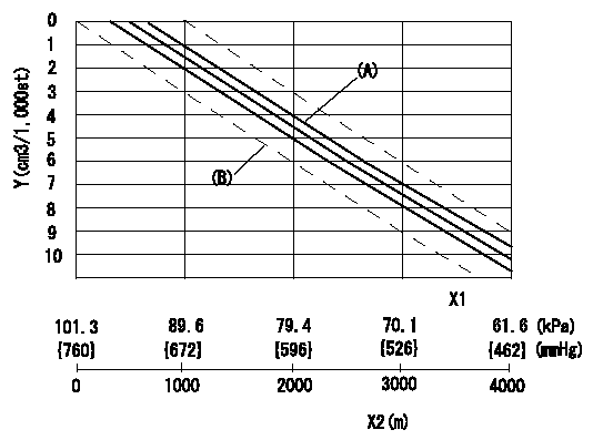
ACS adjustment
Full load injection quantity at high altitudes and ACS adjusting method
1. Full load injection quantity adjustment
(1)Remove the ACS cover and remove the bellows and adjusting shim.
(2)Perform all adjustments as per the adjustment standard except for ACS adjustment.
2. ACS adjustment
(1)Assemble the ACS cover, bellows and adjusting shim.
(2)At pump speed N1, adjust using a shim to obtain the decrease for the altitude shown in the table.
X1 = atmospheric pressure
X2 = altitude
Y = decrease quantity
(A) = adjustment value
(B) = test value
----------
N1=1200r/min
----------
----------
N1=1200r/min
----------
0000001801 STARTING I/Q ADJUSTMENT
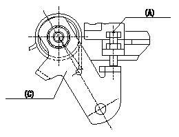
Starting injection quantity adjustment
Adjust the adjusting bolt A so that the starting injection quantity adjustment is within the standards.
Fix using nut (B).
(C) = stopper bolt
----------
----------
----------
----------
0000001901 W-CSD ADJUSTMENT
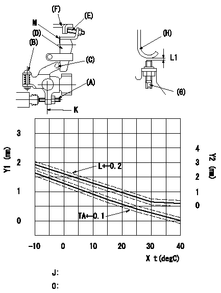
Adjustment of the W-CSD
1. Adjustment of the advance angle of the timer
(1)Determine the timer advance angle from the graph in the figure.
(2)(1) Adjust with the screw (A) so that the timer advance angle determined in the item (1) is obtained.
2. Setting the intermediate lever position
(1)Insert a block gauge L1 = L between the idling set screw (G) and the stopper (H).
(2)When the intermediate lever is perpendicular, fix it so that it contacts the control lever (F).
(3)Align lever (D) perpendicular to the aligning mark.
3. W-CSD lever adjustment
(1)Insert a block gauge L2 determined from the graph (L-t) in the figure between the idling set screw (G) and the stopper (H).
(2)Fix screw (B) so that the W-CSD lever (C)'s roller contacts the intermediate lever (D).
Note:
When inserting the block gauge, separate lever (C) and (D) using screw (B) to prevent excessive force on the lever.
X = temperature t (deg C)
Y1 = timer lift TA (mm)
Y2 = control lever dimension L mm (control lever position
J = graph L - t
O = graph TA - t:
K = intermediate lever perpendicular position
M = aligning mark
----------
L1=0.95+-0.05mm L2=L1+-0.05mm
----------
L1=0.95+-0.05mm
----------
L1=0.95+-0.05mm L2=L1+-0.05mm
----------
L1=0.95+-0.05mm
0000002001 POTENTIOMETER ADJUSTMENT
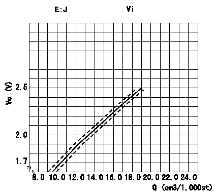
Adjustment of the potentiometer
At pump speed N = N1 and with the control lever angle at a from the idle position (corresponding to a shim thickness of L), convert the injection quantity obtained to a voltage value using the graph and adjust the potentiometer.
Caution: Confirm that the voltage increases when the control lever is turned to the full speed side.
E:J = formula
Vi:Applied voltage
Vo = output voltage
Q = injection quantity
----------
N1=700r/min a=13.3deg L=6.5mm
----------
J=Vo=+-0.05=0.08696Q+0.839 Vi=-V
----------
N1=700r/min a=13.3deg L=6.5mm
----------
J=Vo=+-0.05=0.08696Q+0.839 Vi=-V
Have questions with 104769-2000?
Group cross 104769-2000 ZEXEL
104769-2000
INJECTION-PUMP ASSEMBLY