
Rating:
Information injection-pump assembly
ZEXEL
104749-6630
1047496630
ISUZU
8944277690
8944277690
Cross reference number
ZEXEL
104749-6630
1047496630
ISUZU
8944277690
8944277690
Zexel num
Bosch num
Firm num
Name
Calibration Data:
Adjustment conditions
Test oil
1404 Test oil ISO4113orSAEJ967d
1404 Test oil ISO4113orSAEJ967d
Test oil temperature
degC
45
45
50
Nozzle
105000-2010
Bosch type code
NP-DN12SD12TT
Nozzle holder
105780-2080
Opening pressure
MPa
14.7
14.7
15.19
Opening pressure
kgf/cm2
150
150
155
Injection pipe
Inside diameter - outside diameter - length (mm) mm 2-6-840
Inside diameter - outside diameter - length (mm) mm 2-6-840
Transfer pump pressure
kPa
20
20
20
Transfer pump pressure
kgf/cm2
0.2
0.2
0.2
Direction of rotation (viewed from drive side)
Right R
Right R
Injection timing adjustment
Pump speed
r/min
1250
1250
1250
Average injection quantity
mm3/st.
40.2
39.7
40.7
Difference in delivery
mm3/st.
3.5
Basic
*
Injection timing adjustment_02
Pump speed
r/min
2650
2650
2650
Average injection quantity
mm3/st.
12.1
8.6
15.6
Injection timing adjustment_03
Pump speed
r/min
2350
2350
2350
Average injection quantity
mm3/st.
35.1
33
37.2
Injection timing adjustment_04
Pump speed
r/min
2250
2250
2250
Average injection quantity
mm3/st.
35.2
33.2
37.2
Injection timing adjustment_05
Pump speed
r/min
2000
2000
2000
Average injection quantity
mm3/st.
35.7
33.7
37.7
Injection timing adjustment_06
Pump speed
r/min
1250
1250
1250
Average injection quantity
mm3/st.
40.2
39.2
41.2
Injection timing adjustment_07
Pump speed
r/min
600
600
600
Average injection quantity
mm3/st.
39.2
37.2
41.2
Injection quantity adjustment
Pump speed
r/min
2650
2650
2650
Average injection quantity
mm3/st.
12.1
9.1
15.1
Difference in delivery
mm3/st.
4
Basic
*
Injection quantity adjustment_02
Pump speed
r/min
2800
2800
2800
Average injection quantity
mm3/st.
5
Governor adjustment
Pump speed
r/min
400
400
400
Average injection quantity
mm3/st.
8.8
6.8
10.8
Difference in delivery
mm3/st.
2
Basic
*
Governor adjustment_02
Pump speed
r/min
400
400
400
Average injection quantity
mm3/st.
8.8
6.8
10.8
Governor adjustment_03
Pump speed
r/min
600
600
600
Average injection quantity
mm3/st.
3
Boost compensator adjustment
Pump speed
r/min
925
925
925
Average injection quantity
mm3/st.
9.5
8.5
10.5
Remarks
Refer to additional devices.
Refer to additional devices.
Timer adjustment
Pump speed
r/min
100
100
100
Average injection quantity
mm3/st.
75
60
90
Basic
*
Speed control lever angle
Pump speed
r/min
400
400
400
Average injection quantity
mm3/st.
0
0
0
Remarks
Magnet OFF
Magnet OFF
0000000901
Pump speed
r/min
1250
1250
1250
Overflow quantity
cm3/min
420
288
552
Stop lever angle
Pump speed
r/min
1250
1250
1250
Pressure
kPa
431.5
412
451
Pressure
kgf/cm2
4.4
4.2
4.6
Basic
*
Stop lever angle_02
Pump speed
r/min
600
600
600
Pressure
kPa
255
226
284
Pressure
kgf/cm2
2.6
2.3
2.9
Stop lever angle_03
Pump speed
r/min
1250
1250
1250
Pressure
kPa
431.5
412
451
Pressure
kgf/cm2
4.4
4.2
4.6
Stop lever angle_04
Pump speed
r/min
2000
2000
2000
Pressure
kPa
627.5
598
657
Pressure
kgf/cm2
6.4
6.1
6.7
Stop lever angle_05
Pump speed
r/min
2050
2050
2050
Pressure
kPa
637.5
608
667
Pressure
kgf/cm2
6.5
6.2
6.8
0000001101
Pump speed
r/min
1250
1250
1250
Timer stroke
mm
3.9
3.7
4.1
Basic
*
_02
Pump speed
r/min
550
530
570
Timer stroke
mm
0.5
0.5
0.5
_03
Pump speed
r/min
1250
1250
1250
Timer stroke
mm
3.9
3.6
4.2
_04
Pump speed
r/min
1750
1750
1750
Timer stroke
mm
6.6
6
7.2
_05
Pump speed
r/min
2050
2050
2050
Timer stroke
mm
8.2
7.8
8.6
0000001201
Max. applied voltage
V
8
8
8
Test voltage
V
13
12
14
0000001401
Pump speed
r/min
1250
1250
1250
Average injection quantity
mm3/st.
33
32.5
33.5
Timer stroke variation dT
mm
0.9
0.7
1.1
Basic
*
_02
Pump speed
r/min
1250
1250
1250
Average injection quantity
mm3/st.
33
32
34
Timer stroke variation dT
mm
0.9
0.6
1.2
_03
Pump speed
r/min
1250
1250
1250
Average injection quantity
mm3/st.
25
23.5
26.5
Timer stroke variation dT
mm
1.6
1.1
2.1
Timing setting
K dimension
mm
3.3
3.2
3.4
KF dimension
mm
5.8
5.7
5.9
MS dimension
mm
1.6
1.5
1.7
Control lever angle alpha
Refer to additional devices. deg. 20 16 24
Refer to additional devices. deg. 20 16 24
Control lever angle beta
deg.
37.5
33.5
41.5
Test data Ex:
0000001801 MOTOR LEVER ADJUSTMENT
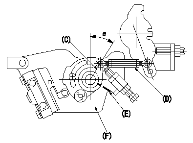
Motor lever adjustment
With the control lever contacting the idle stopper bolt, adjust the length of the rod so that the stepping motor bracket and the motor lever position alignment stamping are aligned.
Nut tightening torque: T1
C:Motor lever
D:Rod
E:Angle aligning stamping position
F:Stepping motor bracket (shape may differ)
----------
T1=3.4~4.9N-m(0.35~0.5kgf-m)
----------
a=(30+-1deg)
----------
T1=3.4~4.9N-m(0.35~0.5kgf-m)
----------
a=(30+-1deg)
0000001901 CAM LEVER ADJUSTMENT
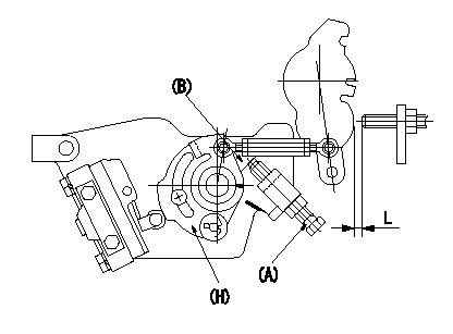
Cam lever adjustment
1. First, loosen the cam stopper bolt (A).
2. Insert a shim (B) between the cam lever and the cam stopper bolt and tighten (A) with shim L inserted. Fix (A) in the position where the idle stopper side shim is loosened.
Nut tightening torque: T2
L1 is lever idle stopper gap measured at partial characteristics.
(A) Cam stopper bolt
(B) Shim
(H) Cam lever
----------
T2=6~9N-m(0.6~0.9kgf-m)
----------
----------
T2=6~9N-m(0.6~0.9kgf-m)
----------
0000002001 IDLE POSITION ADJUSTMENT
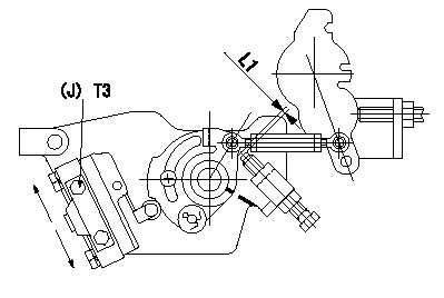
Idle position adjustment
1. Insert a shim L1 between the cam lever and the stopper screw.
2. Move the microswitch in the direction of the arrow so that it turns ON.
3. Turn the microswitch in the direction of the arrow and fix it using the bolts when it turns OFF.
(J) Microswitch fixing bolt
----------
L1=2.5mm
----------
T3=2.0~2.9N-m(0.2~0.3kgf-m)
----------
L1=2.5mm
----------
T3=2.0~2.9N-m(0.2~0.3kgf-m)
0000002101 FULL POSITION ADJUSTMENT
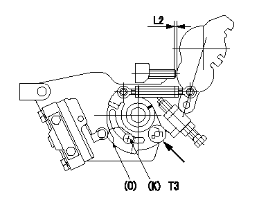
Full position adjustment
(Turn the tension spring pin above the cam lever (in the direction of the arrow) and perform the adjustments below.)
1. Insert a shim L2 between the control lever and the full stopper bolt.
2. Turn the plate clockwise and turn the microswitch ON.
3. Turn the plate counter clockwise and fix it when the microswitch turns OFF.
(K) Bolts (2 locations)
(O) Plate
----------
L2=0.7mm
----------
L2=0.7mm T3=2.0~2.9N-m(0.2~0.3kgf-m)
----------
L2=0.7mm
----------
L2=0.7mm T3=2.0~2.9N-m(0.2~0.3kgf-m)
0000002201 PARTIAL SETTING
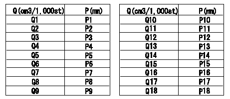
Partial setting
At Np = N1, insert a shim L1 between the control lever and the idle stopper and measure the injection quantity.
Determine the cam lever adjusting shim thickness L for the injection quantity classification in the table.
Q = injection quantity
P = shim thickness at exterior
----------
N1=925r/min L1=3.9mm
----------
Q1=15.0~15.7cm3/1000st Q2=14.3~14.9cm3/1000st Q3=13.7~14.2cm3/1000st Q4=13.0~13.6cm3/1000st Q5=12.3~12.9cm3/1000st Q6=11.6~12.2cm3/1000st Q7=11.0~11.5cm3/1000st Q8=10.5~10.9cm3/1000st Q9=9.8~10.4cm3/1000st Q10=9.2~9.7cm3/1000st Q11=8.6~9.1cm3/1000st Q12=8.1~8.5cm3/1000st Q13=7.7~8.0cm3/1000st Q14=7.2~7.6cm3/1000st Q15=6.8~7.1cm3/1000st Q16=6.4~6.7cm3/1000st Q17=6.0~6.3cm3/1000st Q18=5.6~5.9cm3/1000st P1=3.0mm P2=3.1mm P3=3.2mm P4=3.3mm P5=3.4mm P6=3.5mm P7=3.6mm P8=3.7mm P9=3.8mm P10=3.9mm P11=4.0mm P12=4.1mm P13=4.2mm P14=4.3mm P15=4.4mm P16=4.5mm P17=4.6mm P18=4.7mm
----------
N1=925r/min L1=3.9mm
----------
Q1=15.0~15.7cm3/1000st Q2=14.3~14.9cm3/1000st Q3=13.7~14.2cm3/1000st Q4=13.0~13.6cm3/1000st Q5=12.3~12.9cm3/1000st Q6=11.6~12.2cm3/1000st Q7=11.0~11.5cm3/1000st Q8=10.5~10.9cm3/1000st Q9=9.8~10.4cm3/1000st Q10=9.2~9.7cm3/1000st Q11=8.6~9.1cm3/1000st Q12=8.1~8.5cm3/1000st Q13=7.7~8.0cm3/1000st Q14=7.2~7.6cm3/1000st Q15=6.8~7.1cm3/1000st Q16=6.4~6.7cm3/1000st Q17=6.0~6.3cm3/1000st Q18=5.6~5.9cm3/1000st P1=3.0mm P2=3.1mm P3=3.2mm P4=3.3mm P5=3.4mm P6=3.5mm P7=3.6mm P8=3.7mm P9=3.8mm P10=3.9mm P11=4.0mm P12=4.1mm P13=4.2mm P14=4.3mm P15=4.4mm P16=4.5mm P17=4.6mm P18=4.7mm