
Rating:
Information injection-pump assembly
ZEXEL
104748-2570
1047482570
Cross reference number
ZEXEL
104748-2570
1047482570
Zexel num
Bosch num
Firm num
Name
104748-2570
INJECTION-PUMP ASSEMBLY
Calibration Data:
Adjustment conditions
Test oil
1404 Test oil ISO4113orSAEJ967d
1404 Test oil ISO4113orSAEJ967d
Test oil temperature
degC
45
45
50
Nozzle
105000-2010
Bosch type code
NP-DN12SD12TT
Nozzle holder
105780-2080
Opening pressure
MPa
14.7
14.7
15.19
Opening pressure
kgf/cm2
150
150
155
Injection pipe
Inside diameter - outside diameter - length (mm) mm 2-6-840
Inside diameter - outside diameter - length (mm) mm 2-6-840
Transfer pump pressure
kPa
20
20
20
Transfer pump pressure
kgf/cm2
0.2
0.2
0.2
Direction of rotation (viewed from drive side)
Left L
Left L
Injection timing adjustment
Pump speed
r/min
1000
1000
1000
Average injection quantity
mm3/st.
27.6
27.1
28.1
Difference in delivery
mm3/st.
2
Basic
*
Injection timing adjustment_02
Pump speed
r/min
2700
2700
2700
Average injection quantity
mm3/st.
14.8
11.3
18.3
Injection timing adjustment_03
Pump speed
r/min
2500
2500
2500
Average injection quantity
mm3/st.
26.3
24.3
28.3
Injection timing adjustment_04
Pump speed
r/min
1000
1000
1000
Average injection quantity
mm3/st.
27.6
26.6
28.6
Injection timing adjustment_05
Pump speed
r/min
600
600
600
Average injection quantity
mm3/st.
26.8
24.8
28.8
Injection quantity adjustment
Pump speed
r/min
2700
2700
2700
Average injection quantity
mm3/st.
14.8
11.8
17.8
Difference in delivery
mm3/st.
4.5
Basic
*
Injection quantity adjustment_02
Pump speed
r/min
2900
2900
2900
Average injection quantity
mm3/st.
6
Governor adjustment
Pump speed
r/min
360
360
360
Average injection quantity
mm3/st.
8.1
6.6
9.6
Difference in delivery
mm3/st.
2
Basic
*
Governor adjustment_02
Pump speed
r/min
360
360
360
Average injection quantity
mm3/st.
8.1
6.1
10.1
Governor adjustment_03
Pump speed
r/min
600
600
600
Average injection quantity
mm3/st.
5
Boost compensator adjustment
Pump speed
r/min
700
700
700
Average injection quantity
mm3/st.
15.3
10.8
19.8
Remarks
From idle
From idle
Timer adjustment
Pump speed
r/min
100
100
100
Average injection quantity
mm3/st.
55.3
50.3
60.3
Basic
*
Remarks
Refer to additional devices.
Refer to additional devices.
Speed control lever angle
Pump speed
r/min
360
360
360
Average injection quantity
mm3/st.
0
0
0
Remarks
Magnet OFF
Magnet OFF
0000000901
Pump speed
r/min
1200
1200
1200
Overflow quantity
cm3/min
348
216
480
Stop lever angle
Pump speed
r/min
1200
1200
1200
Pressure
kPa
372.5
343
402
Pressure
kgf/cm2
3.8
3.5
4.1
Basic
*
Stop lever angle_02
Pump speed
r/min
1200
1200
1200
Pressure
kPa
372.5
333
412
Pressure
kgf/cm2
3.8
3.4
4.2
Stop lever angle_03
Pump speed
r/min
1800
1800
1800
Pressure
kPa
510
471
549
Pressure
kgf/cm2
5.2
4.8
5.6
Stop lever angle_04
Pump speed
r/min
2500
2500
2500
Pressure
kPa
667
628
706
Pressure
kgf/cm2
6.8
6.4
7.2
0000001101
Pump speed
r/min
1200
1200
1200
Timer stroke
mm
2.9
2.6
3.2
Basic
*
_02
Pump speed
r/min
1200
1200
1200
Timer stroke
mm
2.9
2.5
3.3
_03
Pump speed
r/min
1800
1800
1800
Timer stroke
mm
5.4
5
5.8
_04
Pump speed
r/min
2500
2500
2500
Timer stroke
mm
8.15
7.7
8.6
0000001201
Max. applied voltage
V
8
8
8
Test voltage
V
13
12
14
0000001401
Pump speed
r/min
1200
1200
1200
Average injection quantity
mm3/st.
16.5
15.5
17.5
Timer stroke variation dT
mm
0.6
0.4
0.8
Basic
*
Timing setting
K dimension
mm
3.3
3.2
3.4
KF dimension
mm
5.8
5.7
5.9
MS dimension
mm
1.6
1.5
1.7
Control lever angle alpha
deg.
0
-1
1
Control lever angle beta
deg.
42
37
47
Control lever angle gamma
deg.
11
10.5
11.5
Test data Ex:
0000001801 CONTROL LEVER ANGLE
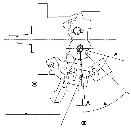
Control lever angle measurement
1. Measure the dimension L from the lever tip to the flange face (A).
2. Measure the lever angle from the pin hole R (plate).
(B): lever angle measuring hole
Alpha = a
beta: b
----------
R=44mm L=15.4~18.1mm
----------
R=44mm L=15.4~18.1mm a=1~-1deg b=37~47deg
----------
R=44mm L=15.4~18.1mm
----------
R=44mm L=15.4~18.1mm a=1~-1deg b=37~47deg
0000001901 STARTING I/Q ADJUSTMENT
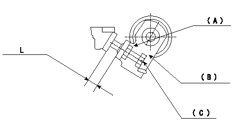
Starting injection quantity adjustment
Adjust adjusting bolt so that the starting injection quantity is within the standard.
Fix using nut.
(A): Lock nut.
(B): Stopping lever
(C): Adjustment bolt
----------
----------
L=5.9~8.2mm
----------
----------
L=5.9~8.2mm
0000002001 W-CSD ADJUSTMENT
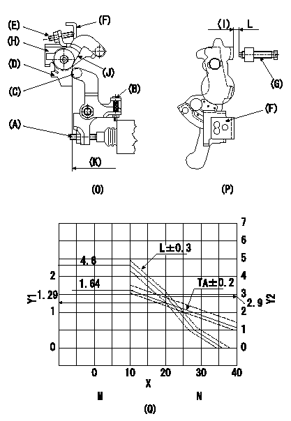
Adjustment of the W-CSD
1. Timer advance adjustment (refer to Fig 1 [O], 3 [Q]).
(1)Determine the timer advance angle from the graph in Fig. 3 (Q).
(2)(1) Adjust with the screw (A) so that the timer advance angle determined in the item (1) is obtained.
2. Setting the intermediate lever position (refer to fig 1 and fig 2)
(1)Insert a block gauge L1 between the idling set screw (G) and the control lever (F).
(2)Align the intermediate lever (D) with the aligning line (J) and position it perpendicularly.
3. W-CSD lever adjustment [refer to fig 1 (O) and fig 2 (P)]
(1)After completing (2) above, remove the block gauge L2.
(2)Insert a block gauge (I) L3 determined from the graph (L-theta) in figure 3 (Q) between the idling set screw (G) and the control lever (F).
(3)Fix screw (B) so that the W-CSD lever (C)'s roller contacts the intermediate lever (D). Fix using the nut.
Note:
The temperature of the wax at adjustment must not exceed a.
X:Temperature theta (deg C)
Y1:Timer stroke TA (mm)
Y2:Control lever L dimension (mm; control lever position)
K:Vertical position
M:TA-theta line
10 <= theta (deg C) <= 20: TA = -0.0355 theta + 1.995
20 <= theta (deg C) <= 57: TA = -0.03515 theta + 1.988
N:L-theta graph
theta (deg C) <= 10: L = 4.6
10 < theta (deg C) <= 20: L = -0.17theta + 6.3
20 < theta (deg C) <= 28.5: L = -0.235 theta + 7.6
28.5 < theta (deg C) <= 36: L = -0.012 theta + 4.32
----------
L1=L=2.9+-0.05mm L2=2.9mm L3=L+-0.05mm a=30degC
----------
----------
L1=L=2.9+-0.05mm L2=2.9mm L3=L+-0.05mm a=30degC
----------
0000002101 POTENTIOMETER ADJUSTMENT
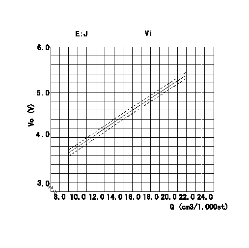
Adjustment of the potentiometer
At pump speed N = N1 r/min and with the control lever angle at a from the idle position (corresponding to a shim thickness of L mm), convert the injection quantity obtained to a voltage value using the graph and adjust the potentiometer.
Vi:Applied voltage
E = conversion expression
Vo = output voltage
Q = injection quantity
----------
N1=700r/min a=12+-0.5deg L=-mm Vi=10V
----------
J+-0.03=0.1352Q+2.42(V) Vi=10V
----------
N1=700r/min a=12+-0.5deg L=-mm Vi=10V
----------
J+-0.03=0.1352Q+2.42(V) Vi=10V
Have questions with 104748-2570?
Group cross 104748-2570 ZEXEL
Nissan
104748-2570
INJECTION-PUMP ASSEMBLY