
Rating:
Information injection-pump assembly
BOSCH
9 460 614 654
9460614654
ZEXEL
104748-2520
1047482520
NISSAN
1670054A01
1670054a01
Cross reference number
BOSCH
9 460 614 654
9460614654
ZEXEL
104748-2520
1047482520
NISSAN
1670054A01
1670054a01
Zexel num
Bosch num
Firm num
Name
104748-2520
9 460 614 654
1670054A01 NISSAN
INJECTION-PUMP ASSEMBLY
CD17 K
CD17 K
Calibration Data:
Adjustment conditions
Test oil
1404 Test oil ISO4113orSAEJ967d
1404 Test oil ISO4113orSAEJ967d
Test oil temperature
degC
45
45
50
Nozzle
105000-2010
Bosch type code
NP-DN12SD12TT
Nozzle holder
105780-2080
Opening pressure
MPa
14.7
14.7
15.19
Opening pressure
kgf/cm2
150
150
155
Injection pipe
Inside diameter - outside diameter - length (mm) mm 2-6-840
Inside diameter - outside diameter - length (mm) mm 2-6-840
Transfer pump pressure
kPa
20
20
20
Transfer pump pressure
kgf/cm2
0.2
0.2
0.2
Direction of rotation (viewed from drive side)
Left L
Left L
Injection timing adjustment
Pump speed
r/min
1000
1000
1000
Average injection quantity
mm3/st.
27.6
27.1
28.1
Difference in delivery
mm3/st.
2.5
Basic
*
Injection timing adjustment_02
Pump speed
r/min
2700
2700
2700
Average injection quantity
mm3/st.
14.8
11.3
18.3
Difference in delivery
mm3/st.
5
Injection timing adjustment_03
Pump speed
r/min
2500
2500
2500
Average injection quantity
mm3/st.
26.3
24.3
28.3
Injection timing adjustment_04
Pump speed
r/min
1000
1000
1000
Average injection quantity
mm3/st.
27.6
26.6
28.6
Difference in delivery
mm3/st.
2.5
Injection timing adjustment_05
Pump speed
r/min
600
600
600
Average injection quantity
mm3/st.
26.8
24.8
28.8
Injection quantity adjustment
Pump speed
r/min
2700
2700
2700
Average injection quantity
mm3/st.
14.8
11.8
17.8
Difference in delivery
mm3/st.
5
Basic
*
Injection quantity adjustment_02
Pump speed
r/min
2900
2900
2900
Average injection quantity
mm3/st.
6
Governor adjustment
Pump speed
r/min
360
360
360
Average injection quantity
mm3/st.
5.2
3.7
6.7
Difference in delivery
mm3/st.
2.5
Basic
*
Governor adjustment_02
Pump speed
r/min
360
360
360
Average injection quantity
mm3/st.
5.2
3.2
7.2
Difference in delivery
mm3/st.
2.5
Governor adjustment_03
Pump speed
r/min
600
600
600
Average injection quantity
mm3/st.
3
Boost compensator adjustment
Pump speed
r/min
700
700
700
Average injection quantity
mm3/st.
15.3
10.8
19.8
Remarks
From idle
From idle
Timer adjustment
Pump speed
r/min
100
100
100
Average injection quantity
mm3/st.
40.3
35.3
45.3
Basic
*
Remarks
Refer to additional devices.
Refer to additional devices.
Speed control lever angle
Pump speed
r/min
360
360
360
Average injection quantity
mm3/st.
0
0
0
Remarks
Magnet OFF
Magnet OFF
0000000901
Pump speed
r/min
1200
1200
1200
Overflow quantity
cm3/min
348
216
480
Stop lever angle
Pump speed
r/min
1200
1200
1200
Pressure
kPa
333.5
304
363
Pressure
kgf/cm2
3.4
3.1
3.7
Basic
*
Stop lever angle_02
Pump speed
r/min
1200
1200
1200
Pressure
kPa
333.5
294
373
Pressure
kgf/cm2
3.4
3
3.8
Stop lever angle_03
Pump speed
r/min
1800
1800
1800
Pressure
kPa
470.5
431
510
Pressure
kgf/cm2
4.8
4.4
5.2
Stop lever angle_04
Pump speed
r/min
2500
2500
2500
Pressure
kPa
637.5
598
677
Pressure
kgf/cm2
6.5
6.1
6.9
0000001101
Pump speed
r/min
1200
1200
1200
Timer stroke
mm
1.8
1.5
2.1
Basic
*
_02
Pump speed
r/min
1200
1200
1200
Timer stroke
mm
1.8
1.4
2.2
_03
Pump speed
r/min
1800
1800
1800
Timer stroke
mm
4.1
3.5
4.7
_04
Pump speed
r/min
2500
2500
2500
Timer stroke
mm
7.35
6.9
7.8
0000001201
Max. applied voltage
V
8
8
8
Test voltage
V
13
12
14
Timing setting
K dimension
mm
3.3
3.2
3.4
KF dimension
mm
5.8
5.7
5.9
MS dimension
mm
1.8
1.7
1.9
Control lever angle alpha
Refer to additional devices. deg. 0 -1 1
Refer to additional devices. deg. 0 -1 1
Control lever angle beta
deg.
44
39
49
Control lever angle gamma
From idle deg. 14 13.5 14.5
From idle deg. 14 13.5 14.5
Test data Ex:
0000001801 CONTROL LEVER ANGLE
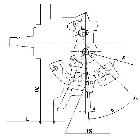
Control lever angle measurement
1. Measure the dimension L from the lever tip to the flange face (A).
2. Measure the lever angle from the pin hole R (plate).
(B): lever angle measuring hole
Alpha = a
beta: b
----------
R=44mm L=15.4~18.1mm
----------
R=44mm L=15.4~18.1mm a=1~-1deg b=13.5~14.5deg
----------
R=44mm L=15.4~18.1mm
----------
R=44mm L=15.4~18.1mm a=1~-1deg b=13.5~14.5deg
0000001901 STARTING I/Q ADJUSTMENT
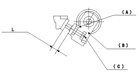
Starting injection quantity adjustment
Adjust adjusting bolt so that the starting injection quantity is within the standard.
Fix using nut.
(A): Lock nut.
(B): Stopping lever
(C): Adjustment bolt
----------
----------
L=5.9~8.2mm
----------
----------
L=5.9~8.2mm
0000002001 W-CSD ADJUSTMENT
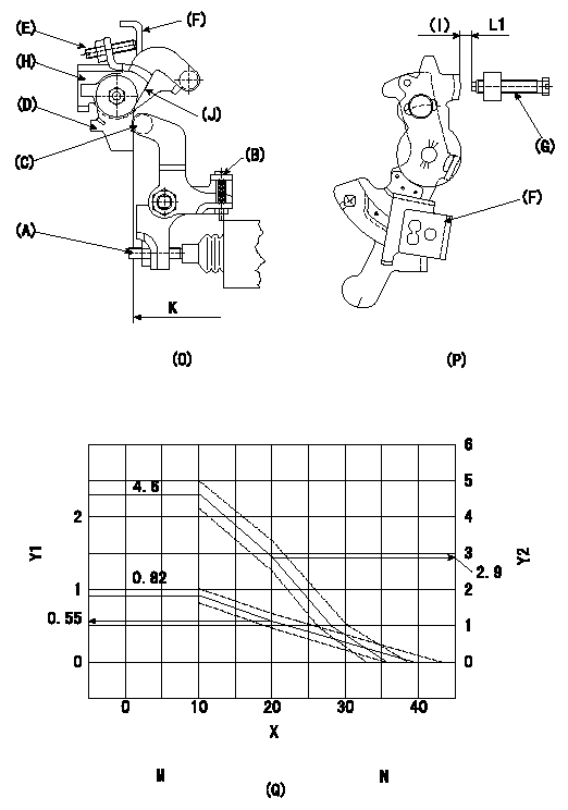
Adjustment of the W-CSD
1. Timer advance adjustment (refer to Fig 1 [O], 3 [Q]).
(1)Determine the timer advance angle from the graph in Fig. 3 (Q).
(2)(1) Adjust with the screw (A) so that the timer advance angle determined in the item (1) is obtained.
2. Setting the intermediate lever position (refer to fig 1 and fig 2)
(1)Insert a block gauge L1 between the idling set screw (G) and the control lever (F).
(2)Align the intermediate lever (D) with the aligning line (J) and position it perpendicularly.
(3)Position screw (E) against the control lever (F) and fix the nut.
3. W-CSD lever adjustment [refer to fig 1 (O) and fig 2 (P)]
(1)Insert a block gauge (I) L2 determined from the graph (L-t) in figure 3 (Q) between the idling set screw (G) and the control lever (F).
(2)Fix screw (B) so that the W-CSD lever (C)'s roller contacts the intermediate lever (D). Fix using the nut.
Note:
The temperature of the wax at adjustment must not exceed a.
X:Temperature t (deg C)
Y1:Timer stroke TA (mm)
Y2:Control lever L dimension (mm; control lever position)
K:Vertical position
M:Graph TA-t:
10 <= t (deg C) <= 20: TA =-0.027t + 1.09
20 <= t (deg C) <= 60: TA = -0.0275 t + 1.1
N:L-theta graph
t (deg C) <= 10: L = 4.6
10 <= t (deg C) <= 20: L = -0.17t + 6.3
20 <= t (deg C) <= 28.5: L = -0.235t + 7.6
28.5 <= t (deg C) <= 36: L = -0.12t + 4.32
----------
L1=4.1+-0.05mm L2=L1+-0.05mm a=30degC
----------
----------
L1=4.1+-0.05mm L2=L1+-0.05mm a=30degC
----------
Have questions with 104748-2520?
Group cross 104748-2520 ZEXEL
Nissan
104748-2520
9 460 614 654
1670054A01
INJECTION-PUMP ASSEMBLY
CD17
CD17