
Rating:
Information injection-pump assembly
BOSCH
9 460 610 271
9460610271
ZEXEL
104748-0343
1047480343
MAZDA
RF7913800A
rf7913800a
Cross reference number
BOSCH
9 460 610 271
9460610271
ZEXEL
104748-0343
1047480343
MAZDA
RF7913800A
rf7913800a
Zexel num
Bosch num
Firm num
Name
Calibration Data:
Adjustment conditions
Test oil
1404 Test oil ISO4113orSAEJ967d
1404 Test oil ISO4113orSAEJ967d
Test oil temperature
degC
45
45
50
Nozzle
105000-2010
Bosch type code
NP-DN12SD12TT
Nozzle holder
105780-2080
Opening pressure
MPa
14.7
14.7
15.19
Opening pressure
kgf/cm2
150
150
155
Injection pipe
Inside diameter - outside diameter - length (mm) mm 2-6-840
Inside diameter - outside diameter - length (mm) mm 2-6-840
Transfer pump pressure
kPa
20
20
20
Transfer pump pressure
kgf/cm2
0.2
0.2
0.2
Direction of rotation (viewed from drive side)
Right R
Right R
Injection timing adjustment
Pump speed
r/min
1375
1375
1375
Average injection quantity
mm3/st.
35.9
35.4
36.4
Difference in delivery
mm3/st.
2.5
Basic
*
Injection timing adjustment_02
Pump speed
r/min
2600
2600
2600
Average injection quantity
mm3/st.
12.8
9.8
15.8
Injection timing adjustment_03
Pump speed
r/min
2325
2325
2325
Average injection quantity
mm3/st.
32.2
30.2
34.2
Injection timing adjustment_04
Pump speed
r/min
1375
1375
1375
Average injection quantity
mm3/st.
35.9
34.9
36.9
Injection timing adjustment_05
Pump speed
r/min
600
600
600
Average injection quantity
mm3/st.
31
29
33
Injection quantity adjustment
Pump speed
r/min
2600
2600
2600
Average injection quantity
mm3/st.
12.8
10.8
14.8
Basic
*
Injection quantity adjustment_02
Pump speed
r/min
2700
2700
2700
Average injection quantity
mm3/st.
6
Governor adjustment
Pump speed
r/min
360
360
360
Average injection quantity
mm3/st.
10
9
11
Difference in delivery
mm3/st.
2
Basic
*
Governor adjustment_02
Pump speed
r/min
360
360
360
Average injection quantity
mm3/st.
10
8
12
Timer adjustment
Pump speed
r/min
100
100
100
Average injection quantity
mm3/st.
42
42
Basic
*
Speed control lever angle
Pump speed
r/min
360
360
360
Average injection quantity
mm3/st.
0
0
0
Remarks
Magnet OFF
Magnet OFF
0000000901
Pump speed
r/min
1375
1375
1375
Overflow quantity
cm3/min
410
278
542
Stop lever angle
Pump speed
r/min
1375
1375
1375
Pressure
kPa
460.5
431
490
Pressure
kgf/cm2
4.7
4.4
5
Basic
*
Stop lever angle_02
Pump speed
r/min
600
600
600
Pressure
kPa
245.5
216
275
Pressure
kgf/cm2
2.5
2.2
2.8
Stop lever angle_03
Pump speed
r/min
1375
1375
1375
Pressure
kPa
460.5
431
490
Pressure
kgf/cm2
4.7
4.4
5
Stop lever angle_04
Pump speed
r/min
1800
1800
1800
Pressure
kPa
578.5
549
608
Pressure
kgf/cm2
5.9
5.6
6.2
Stop lever angle_05
Pump speed
r/min
2325
2325
2325
Pressure
kPa
706
677
735
Pressure
kgf/cm2
7.2
6.9
7.5
0000001101
Pump speed
r/min
1375
1375
1375
Timer stroke
mm
4.2
4
4.4
Basic
*
_02
Pump speed
r/min
1375
1375
1375
Timer stroke
mm
4.2
3.9
4.5
_03
Pump speed
r/min
1800
1800
1800
Timer stroke
mm
6.7
6.1
7.3
_04
Pump speed
r/min
2325
2325
2325
Timer stroke
mm
7.8
7.2
8.4
0000001201
Max. applied voltage
V
8
8
8
Test voltage
V
13
12
14
0000001401
Pump speed
r/min
1375
1375
1375
Average injection quantity
mm3/st.
28.2
27.2
29.2
Timer stroke TA
mm
3.6
3.4
3.8
Basic
*
_02
Pump speed
r/min
1375
1375
1375
Average injection quantity
mm3/st.
28.2
26.7
29.7
Timer stroke TA
mm
3.6
3.3
3.9
_03
Pump speed
r/min
1375
1375
1375
Average injection quantity
mm3/st.
16.1
14.6
17.6
Timer stroke TA
mm
2.4
1.7
3.1
Timing setting
K dimension
mm
3.3
3.2
3.4
KF dimension
mm
5.8
5.7
5.9
MS dimension
mm
1.5
1.4
1.6
Control lever angle alpha
deg.
25
21
29
Control lever angle beta
deg.
45
40
50
Test data Ex:
0000001801 SIDE LINK LEVER ADJUSTMENT
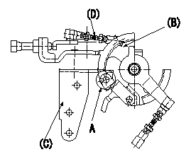
Side link lever adjustment
1. Adjusting the side link lever
(1)Hold the control lever in the position a.
(2)Adjust the length of the rod D so that a pin L1 can pass between the side link B and the actuator bracket C at A, then fix.
Wire length confirmation
Accelerator wire
(1)Idle position: L2
(2)Idle~full: L3
----------
a=0deg L1=Dia.5.8-0.2mm L2=161+-3mm L3=34.0+-4mm
----------
----------
a=0deg L1=Dia.5.8-0.2mm L2=161+-3mm L3=34.0+-4mm
----------
0000001901 W-CSD ADJUSTMENT
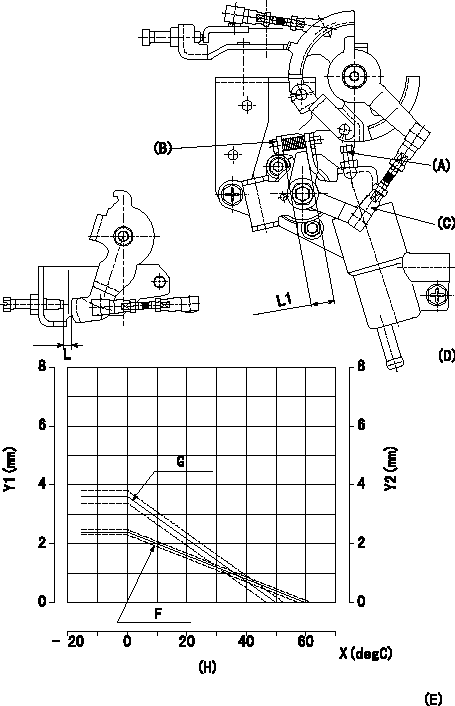
Adjustment of the W-CSD
1. Adjustment of the advance angle of the timer
(1)Determine the timer advance angle from the graph in Fig. 2 (E).
(2)Adjust screw A so that the timer advance angle determined in item (1) is obtained.
2. As shown in figure 1, adjust the screw B so that the distance from the W-FICD lever is L1.
3. Dimension L adjustment
Adjust using turnbuckle C so that the dimension L is as described on the figure 2 E.
(D): figure 1
(H):
Timer stroke: TA = -0.04t + 2.4 (t>= 0 deg C)
Control lever gap: L = -0.072t + 3.6 (t >= 0 deg C)
X:Temperature t
Y1:Timer stroke TA
Y2:Control lever gap: L
----------
L1=12.3+-0.5mm
----------
L1=12.3+-0.5mm L=Lmm
----------
L1=12.3+-0.5mm
----------
L1=12.3+-0.5mm L=Lmm
0000002001 DASHPOT ADJUSTMENT
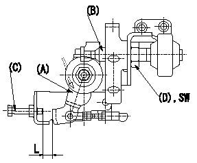
Adjustment of the dash pot
1. Maintain at control lever (A) position a [clearance L between the idle screw and the control lever (A)].
2. In the above condition, adjust the position of the dashpot B so that the end of the dashpot contacts control lever A, and then fix using the switch nut D.
----------
a=13deg L=9+-1mm SW=SW22
----------
L=9+-1mm SW=SW22
----------
a=13deg L=9+-1mm SW=SW22
----------
L=9+-1mm SW=SW22