
Rating:
Information injection-pump assembly
ZEXEL
104748-0340
1047480340
Cross reference number
ZEXEL
104748-0340
1047480340
Zexel num
Bosch num
Firm num
Name
Calibration Data:
Adjustment conditions
Test oil
1404 Test oil ISO4113orSAEJ967d
1404 Test oil ISO4113orSAEJ967d
Test oil temperature
degC
45
45
50
Nozzle
105000-2010
Bosch type code
NP-DN12SD12TT
Nozzle holder
105780-2080
Opening pressure
MPa
14.7
14.7
15.19
Opening pressure
kgf/cm2
150
150
155
Injection pipe
Inside diameter - outside diameter - length (mm) mm 2-6-840
Inside diameter - outside diameter - length (mm) mm 2-6-840
Transfer pump pressure
kPa
20
20
20
Transfer pump pressure
kgf/cm2
0.2
0.2
0.2
Direction of rotation (viewed from drive side)
Right R
Right R
Injection timing adjustment
Pump speed
r/min
1375
1375
1375
Average injection quantity
mm3/st.
35.7
35.2
36.2
Difference in delivery
mm3/st.
2.5
Basic
*
Oil temperature
degC
50
48
52
Injection timing adjustment_02
Pump speed
r/min
1375
1365
1385
Average injection quantity
mm3/st.
35.7
34.7
36.7
Difference in delivery
mm3/st.
3
Oil temperature
degC
50
48
52
Injection timing adjustment_03
Pump speed
r/min
2325
2315
2335
Average injection quantity
mm3/st.
32
30.4
33.6
Oil temperature
degC
52
50
54
Injection quantity adjustment
Pump speed
r/min
2600
2600
2600
Average injection quantity
mm3/st.
12.7
10.7
14.7
Difference in delivery
mm3/st.
4
Basic
*
Oil temperature
degC
55
52
58
Injection quantity adjustment_02
Pump speed
r/min
2700
2700
2700
Average injection quantity
mm3/st.
6
Oil temperature
degC
55
52
58
Injection quantity adjustment_03
Pump speed
r/min
2600
2590
2610
Average injection quantity
mm3/st.
12.7
9.7
15.7
Oil temperature
degC
55
52
58
Governor adjustment
Pump speed
r/min
360
360
360
Average injection quantity
mm3/st.
8
7
9
Difference in delivery
mm3/st.
2
Basic
*
Oil temperature
degC
48
46
50
Governor adjustment_02
Pump speed
r/min
360
350
370
Average injection quantity
mm3/st.
8
6
10
Difference in delivery
mm3/st.
2.5
Oil temperature
degC
48
46
50
Timer adjustment
Pump speed
r/min
100
100
100
Average injection quantity
mm3/st.
42
42
Basic
*
Oil temperature
degC
48
46
50
Speed control lever angle
Pump speed
r/min
360
360
360
Average injection quantity
mm3/st.
0
0
0
Oil temperature
degC
48
46
50
Remarks
Magnet OFF at idling position
Magnet OFF at idling position
0000000901
Pump speed
r/min
1375
1375
1375
Overflow quantity
cm3/min
410
280
540
Oil temperature
degC
50
48
52
Stop lever angle
Pump speed
r/min
1375
1375
1375
Pressure
kPa
461
432
490
Pressure
kgf/cm2
4.7
4.4
5
Basic
*
Oil temperature
degC
50
48
52
Stop lever angle_02
Pump speed
r/min
1375
1365
1385
Pressure
kPa
460.5
431
490
Pressure
kgf/cm2
4.7
4.4
5
Oil temperature
degC
50
48
52
Stop lever angle_03
Pump speed
r/min
1800
1790
1810
Pressure
kPa
578.5
549
608
Pressure
kgf/cm2
5.9
5.6
6.2
Oil temperature
degC
50
48
52
0000001101
Pump speed
r/min
1375
1375
1375
Timer stroke
mm
4.2
4
4.4
Basic
*
Oil temperature
degC
50
48
52
_02
Pump speed
r/min
1375
1365
1385
Timer stroke
mm
4.2
4
4.4
Oil temperature
degC
50
48
52
_03
Pump speed
r/min
1800
1790
1810
Timer stroke
mm
6.7
6.3
7.1
Oil temperature
degC
50
48
52
0000001201
Max. applied voltage
V
8
8
8
Test voltage
V
13
12
14
0000001401
Pump speed
r/min
1375
1375
1375
Average injection quantity
mm3/st.
28
27
29
Timer stroke TA
mm
3.6
3.4
3.8
Basic
*
Oil temperature
degC
50
48
52
_02
Pump speed
r/min
1375
1375
1375
Average injection quantity
mm3/st.
16
15
17
Timer stroke TA
mm
2.4
1.9
2.9
Basic
*
Oil temperature
degC
50
48
52
_03
Pump speed
r/min
1375
1365
1385
Average injection quantity
mm3/st.
28
26
30
Timer stroke TA
mm
3.6
3.4
3.8
Oil temperature
degC
50
48
52
Timing setting
K dimension
mm
3.3
3.2
3.4
KF dimension
mm
5.8
5.7
5.9
MS dimension
mm
1.5
1.4
1.6
Control lever angle alpha
deg.
25
21
29
Control lever angle beta
deg.
45
40
50
Test data Ex:
0000001801 SIDE LINK LEVER ADJUSTMENT
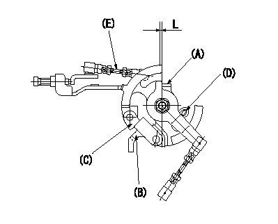
Side link lever adjustment
1. Hold the control lever at position a.
2. Hold the side link lever (B)(C) against the stopper (D).
3. Adjust the length of the connecting rod (E) so that there is a gap L1 between the side link lever's hook (A) and (B)(C).
----------
a=0deg L=1+0.5mm
----------
L=1+0.5mm
----------
a=0deg L=1+0.5mm
----------
L=1+0.5mm
0000001901 W-CSD ADJUSTMENT
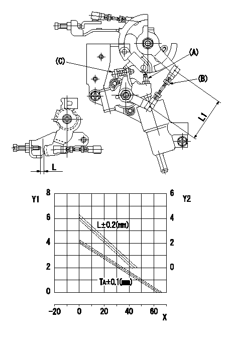
Adjustment of the W-CSD
1. Adjust using screw (A) so that the timer advance is as determined from the graph.
2. Adjust using the turnbuckle (B) to obtain L1.
3. Adjust so that the control lever gap L is as determined from the graph.
Y1 = timer stroke TA (mm)
Y2 = control lever gap L (mm)
X = temperature t (deg C)
----------
L1=50.7+-1mm
----------
L1=50.7+-1mm
----------
L1=50.7+-1mm
----------
L1=50.7+-1mm
0000002001 DASHPOT ADJUSTMENT
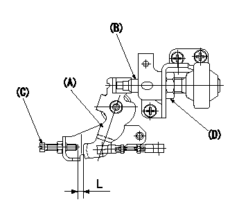
Adjustment of the dash pot
1. Move the control lever (A) a from idle (gap between idle screw (C) and control lever is L).
2. Adjust the position of the dashpot (B) so that the end of the dashpot contacts the control lever.
3. Fix (D) using the SW22 nut.
----------
a=13deg L=9+-1mm
----------
L=9+-1mm
----------
a=13deg L=9+-1mm
----------
L=9+-1mm