Rating:
Information injection-pump assembly
ZEXEL
104740-6080
1047406080
Cross reference number
ZEXEL
104740-6080
1047406080
Zexel num
Bosch num
Firm num
Name
104740-6080
INJECTION-PUMP ASSEMBLY
Calibration Data:
Adjustment conditions
Test oil
1404 Test oil ISO4113orSAEJ967d
1404 Test oil ISO4113orSAEJ967d
Test oil temperature
degC
45
45
50
Nozzle
105780-0060
Bosch type code
NP-DN0SD1510
Nozzle holder
105780-2150
Opening pressure
MPa
13
13
13.3
Opening pressure
kgf/cm2
133
133
136
Injection pipe
157805-7320
Injection pipe
Inside diameter - outside diameter - length (mm) mm 2-6-450
Inside diameter - outside diameter - length (mm) mm 2-6-450
Joint assembly
157641-4720
Tube assembly
157641-4020
Transfer pump pressure
kPa
20
20
20
Transfer pump pressure
kgf/cm2
0.2
0.2
0.2
Direction of rotation (viewed from drive side)
Right R
Right R
Injection timing adjustment
Pump speed
r/min
1300
1300
1300
Average injection quantity
mm3/st.
37.2
36.7
37.7
Difference in delivery
mm3/st.
3.5
Basic
*
Oil temperature
degC
50
48
52
Injection timing adjustment_02
Pump speed
r/min
500
500
500
Average injection quantity
mm3/st.
37.7
33.7
41.7
Oil temperature
degC
48
46
50
Injection timing adjustment_03
Pump speed
r/min
600
600
600
Average injection quantity
mm3/st.
37.5
34.5
40.5
Oil temperature
degC
50
48
52
Injection timing adjustment_04
Pump speed
r/min
1300
1300
1300
Average injection quantity
mm3/st.
37.2
36.2
38.2
Difference in delivery
mm3/st.
3.5
Basic
*
Oil temperature
degC
50
48
52
Injection timing adjustment_05
Pump speed
r/min
2250
2250
2250
Average injection quantity
mm3/st.
37.6
35.6
39.6
Oil temperature
degC
52
50
54
Injection quantity adjustment
Pump speed
r/min
2600
2600
2600
Average injection quantity
mm3/st.
17.1
14.1
20.1
Difference in delivery
mm3/st.
5
Basic
*
Oil temperature
degC
55
52
58
Injection quantity adjustment_02
Pump speed
r/min
2800
2800
2800
Average injection quantity
mm3/st.
5
Oil temperature
degC
55
52
58
Injection quantity adjustment_03
Pump speed
r/min
2600
2600
2600
Average injection quantity
mm3/st.
17.1
14.1
20.1
Difference in delivery
mm3/st.
5
Basic
*
Oil temperature
degC
55
52
58
Governor adjustment
Pump speed
r/min
435
435
435
Average injection quantity
mm3/st.
12.5
10.5
14.5
Difference in delivery
mm3/st.
2
Basic
*
Oil temperature
degC
48
46
50
Governor adjustment_02
Pump speed
r/min
435
435
435
Average injection quantity
mm3/st.
12.5
10.5
14.5
Difference in delivery
mm3/st.
2
Basic
*
Oil temperature
degC
48
46
50
Timer adjustment
Pump speed
r/min
100
100
100
Average injection quantity
mm3/st.
51.5
41.5
61.5
Basic
*
Oil temperature
degC
48
46
50
Remarks
IDLE
IDLE
Timer adjustment_02
Pump speed
r/min
100
100
100
Average injection quantity
mm3/st.
51.5
41.5
61.5
Oil temperature
degC
48
46
50
Speed control lever angle
Pump speed
r/min
435
435
435
Average injection quantity
mm3/st.
0
0
0
Oil temperature
degC
48
46
50
Remarks
Magnet OFF at idling position
Magnet OFF at idling position
0000000901
Pump speed
r/min
1250
1250
1250
Overflow quantity
cm3/min
620
490
750
Oil temperature
degC
50
48
52
Stop lever angle
Pump speed
r/min
1250
1250
1250
Pressure
kPa
392
372
412
Pressure
kgf/cm2
4
3.8
4.2
Basic
*
Oil temperature
degC
50
48
52
Stop lever angle_02
Pump speed
r/min
1250
1250
1250
Pressure
kPa
392
372
412
Pressure
kgf/cm2
4
3.8
4.2
Basic
*
Oil temperature
degC
50
48
52
Stop lever angle_03
Pump speed
r/min
2100
2100
2100
Pressure
kPa
608
569
647
Pressure
kgf/cm2
6.2
5.8
6.6
Oil temperature
degC
52
50
54
0000001101
Pump speed
r/min
1250
1250
1250
Timer stroke
mm
2.6
2.4
2.8
Basic
*
Oil temperature
degC
50
48
52
_02
Pump speed
r/min
850
850
850
Timer stroke
mm
0.5
0.1
1.3
Oil temperature
degC
50
48
52
_03
Pump speed
r/min
1250
1250
1250
Timer stroke
mm
2.6
2.4
2.8
Basic
*
Oil temperature
degC
50
48
52
_04
Pump speed
r/min
1750
1750
1750
Timer stroke
mm
5
4.6
5.4
Oil temperature
degC
50
48
52
_05
Pump speed
r/min
2100
2100
2100
Timer stroke
mm
6.2
5.9
6.6
Oil temperature
degC
52
50
54
0000001201
Max. applied voltage
V
8
8
8
Test voltage
V
13
12
14
0000001401
Pump speed
r/min
1250
1250
1250
Average injection quantity
mm3/st.
22.2
21.2
23.2
Timer stroke TA
mm
2.2
2.2
2.2
Timer stroke variation dT
mm
0.4
0.2
0.6
Basic
*
Oil temperature
degC
50
48
52
_02
Pump speed
r/min
1250
1250
1250
Average injection quantity
mm3/st.
22.2
21.2
23.2
Timer stroke variation dT
mm
0.4
0.2
0.6
Basic
*
Oil temperature
degC
50
48
52
_03
Pump speed
r/min
1250
1250
1250
Average injection quantity
mm3/st.
10.8
9.8
11.8
Timer stroke variation dT
mm
1
0.6
1.4
Oil temperature
degC
50
48
52
Timing setting
K dimension
mm
3.3
3.2
3.4
KF dimension
mm
5.3
5.2
5.4
MS dimension
mm
0.7
0.6
0.8
Pre-stroke
mm
0.1
0.08
0.12
Control lever angle alpha
deg.
20
16
24
Control lever angle beta
deg.
45
40
50
Test data Ex:
0000001801 POTENTIOMETER ADJUSTMENT
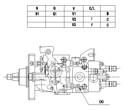
Adjustment of the potentiometer
Adjustment method (supply voltage Vi, dummy bolt method)
1. Hold the dummy bolt (A) against the control lever at position N = N1 and Q = Q1 and fix using the lock nut.
2. When adjusting the potentiometer, position the control lever against the dummy bolt (A) and adjust so that the output voltage is V1.
3. After adjustment, remove the dummy bolt and confirm that the potentiometer output voltage at the control lever's idling and full positions is as specified in the table.
(A) Dummy bolt
N:Pump speed
V:Output voltage
Q:Injection quantity
C/L: control lever position
I:Idling lever position
F:Full speed lever position
B:Adjusting point
C:Checking point
----------
N1=1000r/min Q1=18.3+-1.0mm3/st V1=4.95+-0.03V Vi=10V
----------
N1=1000r/min V1=4.95+-0.03V V2=(2.00+-0.45V) V3=(9.39+-0.65V) Q1=18.3+-1.0mm3/st
----------
N1=1000r/min Q1=18.3+-1.0mm3/st V1=4.95+-0.03V Vi=10V
----------
N1=1000r/min V1=4.95+-0.03V V2=(2.00+-0.45V) V3=(9.39+-0.65V) Q1=18.3+-1.0mm3/st
0000001901 W-CSD ADJUSTMENT
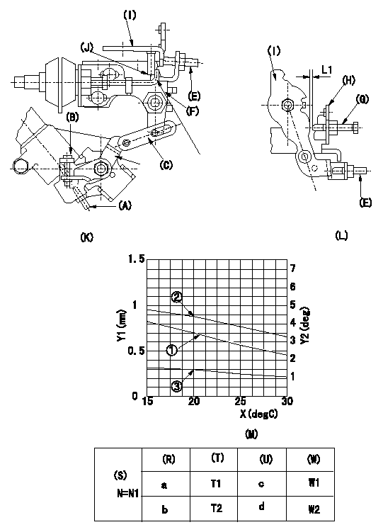
Adjustment of the W-CSD
1. Adjustment of the timer stroke
Adjust using screw (A) so that the timer stroke is the value determined using the graph (M). [(K), (M)]
2. Adjustment of the position of the intermediate lever.
Insert the shim (L1) between the control lever (I) and the idle set screw (G).
Align the intermediate lever (F) with the aligning mark (J) and fix the intermediate lever screw (E) so that it contacts the control lever. [(K), (L)]
3. Adjustment of the FICD
Insert the shim (L2) between the control lever (I) and the idle set screw (G).
Fix with the adjusting screw to the position where the CSD lever (C) actuates the intermediate lever through the rod (D). (K), (L), (M)
(O) timer stroke adjustment (mm) - (1): TA = -0.0235t + 1.17
(P) Lever angle (deg) - (2): Theta 1 = -0.0625 t + 5.65 (-20 deg C <= t <= 20 deg C)
Theta 2 = -0.1108t + 6.62 (20 deg C =< t =< 60 deg C)
(Q) lever position (mm) - (3): L1 = -0.02075t + 1.878 (-20 deg C <= t <= 20 deg C)
L2 = -0.03900t + 2.277 (20 deg C =< t =< 60 deg C)
The (Q) indicates the clearance between the control lever and the idle set screw.
(R): cooling water temperature (deg C)
(S): cooling water temperature: increase direction
N:Pump speed
X:Temperature t (deg C)
Y1:Timer stroke TA (mm)
Y2:Control lever position at theta L (deg, mm)
(T): Timer piston stroke (mm)
(U): Lever angle (deg)
(W): Lever position (mm)
----------
L1=2.0+-0.05mm L2=L1+-0.05mm
----------
N1=500r/min a=20degC b=-20degC c=4.4deg+-1deg d=6.9deg+-3deg T1=0.7+-0.2mm T2=1.6+-0.4mm W1=1.5+-0.3mm W2=2.3+-1mm L1=2.0+-0.05mm
----------
L1=2.0+-0.05mm L2=L1+-0.05mm
----------
N1=500r/min a=20degC b=-20degC c=4.4deg+-1deg d=6.9deg+-3deg T1=0.7+-0.2mm T2=1.6+-0.4mm W1=1.5+-0.3mm W2=2.3+-1mm L1=2.0+-0.05mm
Have questions with 104740-6080?
Group cross 104740-6080 ZEXEL
Isuzu
Isuzu
104740-6080
INJECTION-PUMP ASSEMBLY