Rating:
Information injection-pump assembly
ZEXEL
104740-2373
1047402373
NISSAN
167001C310
167001c310
Cross reference number
ZEXEL
104740-2373
1047402373
NISSAN
167001C310
167001c310
Zexel num
Bosch num
Firm num
Name
Calibration Data:
Adjustment conditions
Test oil
1404 Test oil ISO4113orSAEJ967d
1404 Test oil ISO4113orSAEJ967d
Test oil temperature
degC
45
45
50
Nozzle
105780-0060
Bosch type code
NP-DN0SD1510
Nozzle holder
105780-2150
Opening pressure
MPa
13
13
13.3
Opening pressure
kgf/cm2
133
133
136
Injection pipe
157805-7320
Injection pipe
Inside diameter - outside diameter - length (mm) mm 2-6-450
Inside diameter - outside diameter - length (mm) mm 2-6-450
Joint assembly
157641-4720
Tube assembly
157641-4020
Transfer pump pressure
kPa
20
20
20
Transfer pump pressure
kgf/cm2
0.2
0.2
0.2
Direction of rotation (viewed from drive side)
Left L
Left L
Injection timing adjustment
Pump speed
r/min
900
900
900
Boost pressure
kPa
0
0
0
Boost pressure
mmHg
0
0
0
Average injection quantity
mm3/st.
31.8
31.3
32.3
Difference in delivery
mm3/st.
2.5
Basic
*
Remarks
Full
Full
Injection timing adjustment_02
Pump speed
r/min
900
900
900
Boost pressure
kPa
43.35
42
44.7
Boost pressure
mmHg
325
315
335
Average injection quantity
mm3/st.
45.1
44.6
45.6
Difference in delivery
mm3/st.
2.5
Basic
*
Remarks
CBS
CBS
Injection timing adjustment_03
Pump speed
r/min
2700
2700
2700
Boost pressure
kPa
66.65
65.3
68
Boost pressure
mmHg
500
490
510
Average injection quantity
mm3/st.
21.4
13.9
28.9
Injection timing adjustment_04
Pump speed
r/min
2550
2550
2550
Boost pressure
kPa
66.65
65.3
68
Boost pressure
mmHg
500
490
510
Average injection quantity
mm3/st.
37.5
36
39
Injection timing adjustment_05
Pump speed
r/min
2400
2400
2400
Boost pressure
kPa
66.65
65.3
68
Boost pressure
mmHg
500
490
510
Average injection quantity
mm3/st.
45.9
42.4
49.4
Injection timing adjustment_06
Pump speed
r/min
2200
2200
2200
Boost pressure
kPa
66.65
65.3
68
Boost pressure
mmHg
500
490
510
Average injection quantity
mm3/st.
47.6
44.1
51.1
Injection timing adjustment_07
Pump speed
r/min
1800
1800
1800
Boost pressure
kPa
66.65
65.3
68
Boost pressure
mmHg
500
490
510
Average injection quantity
mm3/st.
51.3
48.3
54.3
Injection timing adjustment_08
Pump speed
r/min
1400
1400
1400
Boost pressure
kPa
66.65
65.3
68
Boost pressure
mmHg
500
490
510
Average injection quantity
mm3/st.
51.6
48.6
54.6
Injection timing adjustment_09
Pump speed
r/min
900
900
900
Boost pressure
kPa
0
0
0
Boost pressure
mmHg
0
0
0
Average injection quantity
mm3/st.
31.8
30.8
32.8
Remarks
Full
Full
Injection timing adjustment_10
Pump speed
r/min
900
900
900
Boost pressure
kPa
43.35
42
44.7
Boost pressure
mmHg
325
315
335
Average injection quantity
mm3/st.
45.1
44.1
46.1
Remarks
CBS
CBS
Injection timing adjustment_11
Pump speed
r/min
600
600
600
Boost pressure
kPa
0
0
0
Boost pressure
mmHg
0
0
0
Average injection quantity
mm3/st.
35.7
33.7
37.7
Injection quantity adjustment
Pump speed
r/min
2550
2550
2550
Boost pressure
kPa
66.65
65.3
68
Boost pressure
mmHg
500
490
510
Average injection quantity
mm3/st.
37.5
36.5
38.5
Basic
*
Injection quantity adjustment_02
Pump speed
r/min
2950
2950
2950
Boost pressure
kPa
66.65
65.3
68
Boost pressure
mmHg
500
490
510
Average injection quantity
mm3/st.
6
Governor adjustment
Pump speed
r/min
400
400
400
Boost pressure
kPa
0
0
0
Boost pressure
mmHg
0
0
0
Average injection quantity
mm3/st.
10.5
9.5
11.5
Basic
*
Governor adjustment_02
Pump speed
r/min
800
800
800
Boost pressure
kPa
0
0
0
Boost pressure
mmHg
0
0
0
Average injection quantity
mm3/st.
5
Governor adjustment_03
Pump speed
r/min
400
400
400
Boost pressure
kPa
0
0
0
Boost pressure
mmHg
0
0
0
Average injection quantity
mm3/st.
10.5
9
12
Boost compensator adjustment
Pump speed
r/min
700
700
700
Boost pressure
kPa
0
0
0
Boost pressure
mmHg
0
0
0
Average injection quantity
mm3/st.
18.4
11.9
24.9
Timer adjustment
Pump speed
r/min
100
100
100
Boost pressure
kPa
0
0
0
Boost pressure
mmHg
0
0
0
Average injection quantity
mm3/st.
65
60
70
Basic
*
Speed control lever angle
Pump speed
r/min
400
400
400
Boost pressure
kPa
0
0
0
Boost pressure
mmHg
0
0
0
Average injection quantity
mm3/st.
0
0
0
Remarks
Magnet OFF
Magnet OFF
0000000901
Pump speed
r/min
900
900
900
Boost pressure
kPa
66.65
65.3
68
Boost pressure
mmHg
500
490
510
Overflow quantity
cm3/min
378
246
510
Stop lever angle
Pump speed
r/min
900
900
900
Boost pressure
kPa
66.65
65.3
68
Boost pressure
mmHg
500
490
510
Pressure
kPa
382.5
353
412
Pressure
kgf/cm2
3.9
3.6
4.2
Basic
*
Stop lever angle_02
Pump speed
r/min
600
600
600
Boost pressure
kPa
66.65
65.3
68
Boost pressure
mmHg
500
490
510
Pressure
kPa
313.5
284
343
Pressure
kgf/cm2
3.2
2.9
3.5
Stop lever angle_03
Pump speed
r/min
900
900
900
Boost pressure
kPa
66.65
65.3
68
Boost pressure
mmHg
500
490
510
Pressure
kPa
382.5
353
412
Pressure
kgf/cm2
3.9
3.6
4.2
Stop lever angle_04
Pump speed
r/min
1400
1400
1400
Boost pressure
kPa
66.65
65.3
68
Boost pressure
mmHg
500
490
510
Pressure
kPa
490.5
461
520
Pressure
kgf/cm2
5
4.7
5.3
Stop lever angle_05
Pump speed
r/min
2200
2200
2200
Boost pressure
kPa
66.65
65.3
68
Boost pressure
mmHg
500
490
510
Pressure
kPa
667
628
706
Pressure
kgf/cm2
6.8
6.4
7.2
0000001101
Pump speed
r/min
900
900
900
Boost pressure
kPa
66.65
65.3
68
Boost pressure
mmHg
500
490
510
Timer stroke
mm
3
2.8
3.2
Basic
*
_02
Pump speed
r/min
600
600
600
Boost pressure
kPa
66.65
65.3
68
Boost pressure
mmHg
500
490
510
Timer stroke
mm
1
0.3
1.7
_03
Pump speed
r/min
900
900
900
Boost pressure
kPa
66.65
65.3
68
Boost pressure
mmHg
500
490
510
Timer stroke
mm
3
2.7
3.3
_04
Pump speed
r/min
1400
1400
1400
Boost pressure
kPa
66.65
65.3
68
Boost pressure
mmHg
500
490
510
Timer stroke
mm
5.9
5.4
6.4
_05
Pump speed
r/min
1800
1800
1800
Boost pressure
kPa
66.65
65.3
68
Boost pressure
mmHg
500
490
510
Timer stroke
mm
8.2
7.6
8.8
_06
Pump speed
r/min
2200
2200
2200
Boost pressure
kPa
66.65
65.3
68
Boost pressure
mmHg
500
490
510
Timer stroke
mm
8.9
8.4
9.4
0000001201
Max. applied voltage
V
8
8
8
Test voltage
V
13
12
14
0000001401
Pump speed
r/min
900
900
900
Boost pressure
kPa
0
0
0
Boost pressure
mmHg
0
0
0
Average injection quantity
mm3/st.
25.9
25.4
26.4
Timer stroke variation dT
mm
0.3
0.1
0.5
Basic
*
_02
Pump speed
r/min
900
900
900
Boost pressure
kPa
0
0
0
Boost pressure
mmHg
0
0
0
Average injection quantity
mm3/st.
25.9
24.9
26.9
Timer stroke variation dT
mm
0.35
0
0.7
_03
Pump speed
r/min
900
900
900
Boost pressure
kPa
0
0
0
Boost pressure
mmHg
0
0
0
Average injection quantity
mm3/st.
17.5
16
19
Timer stroke variation dT
mm
0.8
0.3
1.3
Timing setting
K dimension
mm
3.3
3.2
3.4
KF dimension
mm
6.29
6.19
6.39
MS dimension
mm
0.9
0.8
1
BCS stroke
mm
4.6
4.4
4.8
Control lever angle alpha
deg.
25
23
27
Control lever angle beta
deg.
42
37
47
Control lever angle gamma
deg.
9
8.5
9.5
Test data Ex:
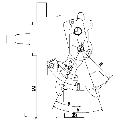
0000001801 CONTROL LEVER ANGLE

Control lever angle measurement
1. Measure the dimension L from the lever tip to the flange face (A).
2. Measure the lever angle from the pin hole R (plate).
(B): lever angle measuring hole
Alpha = a
beta: b
----------
R=61.5mm L=25.7~29.7mm
----------
R=61.5mm L=25.7~29.7mm
----------
R=61.5mm L=25.7~29.7mm
----------
R=61.5mm L=25.7~29.7mm
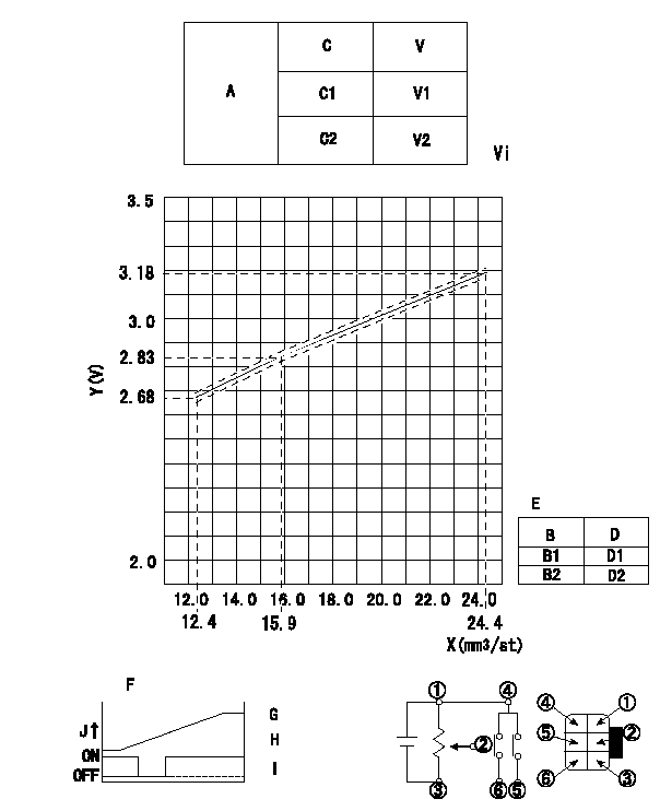
0000001901 POTENTIOMETER ADJUSTMENT

Adjustment of the potentiometer
At pump speed N1 and a control lever position a from idle (gap L1), measure the injection quantity and convert it to a voltage value. Then adjust the potentiometer.
Voltage conversion formula: V+-0.03 = 0.04163Q+2.1637
A:Potentiometer performance standards
C:Position of the control lever
C1:Idle
C2:Full speed
V:Potentiometer voltage
E:Standards for the potentiometer's ON - OFF switch
B:Conversion point
B1:OFF-->ON
B2:OFF-->ON
D:Lever opening (from idle)
Vi:Applied voltage
F:Connecting diagram for the potentiometer
G:Output when (2) and (3) connected.
H:When (4) or (6) connected: switch OFF to ON.
I:When (4) or (5) connected: switch ON to OFF.
J:Output
----------
N1=700r/min a=9deg L1=5.95mm
----------
V1=1.43+-0.4V V2=8.43+-1.47V Vi=10V D1=5+-3deg D2=21.5++deg
----------
N1=700r/min a=9deg L1=5.95mm
----------
V1=1.43+-0.4V V2=8.43+-1.47V Vi=10V D1=5+-3deg D2=21.5++deg
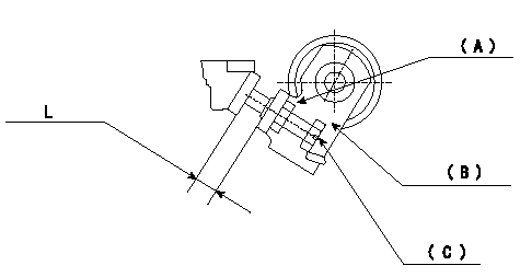
0000002001 STARTING I/Q ADJUSTMENT

Starting injection quantity adjustment
Adjust adjusting bolt so that the starting injection quantity is within the standard.
Fix using nut.
(A): Lock nut.
(B): Stopping lever
(C): Adjustment bolt
----------
----------
L=5~10mm
----------
----------
L=5~10mm
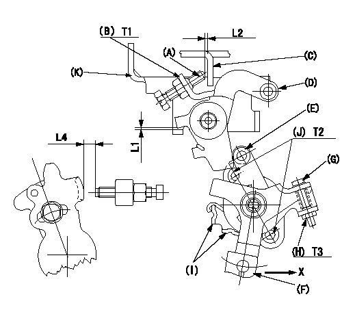
0000002101 M-CSD ADJUSTMENT

M-CSD adjustment
1. Fixing intermediate lever screw (A) [roller (E) must not contact intermediate lever (D)]
(1)Hold the control lever (C) in the idle position.
(2)Insert a block gauge (thickness gauge) L1 between the intermediate lever (D) and the bracket (K). Adjust screw (A) so that the distance between screw A and the control lever to L2 and fix using the nut (B).
2. Fixing the M-CSD stopper (I)
Pull the CSD lever F in the direction X until it contacts the stopper I and tighten the socket head bolt J when the timer stroke is L3.
3. Screw (G) adjustment
(1)Adjust using the screw G so that the roller E contacts the intermediate lever D, then fix using the nut H.
(2)Pull the CSD lever F in the direction X until it contacts the stopper I and confirm that the control lever shim thickness (lever position) is L4.
Note: Use screw (A) to fine-adjust the lever position. [Maintain a gap L2 between the screw (A) and the control lever (C).]
----------
L1=1+-0.1mm L2=1~2mm L3=0.82+-0.2mm L4=3.8+-0.5mm
----------
T1=6~9N-m(0.6~0.9kgf-m) T2=5~7N-m(0.5~0.7kgf-m) T3=2~3N-m(0.2~0.3kgf-m) L1=1+-0.1mm L2=1~2mm L4=3.8+-0.5mm
----------
L1=1+-0.1mm L2=1~2mm L3=0.82+-0.2mm L4=3.8+-0.5mm
----------
T1=6~9N-m(0.6~0.9kgf-m) T2=5~7N-m(0.5~0.7kgf-m) T3=2~3N-m(0.2~0.3kgf-m) L1=1+-0.1mm L2=1~2mm L4=3.8+-0.5mm