
Rating:
Information injection-pump assembly
BOSCH
9 400 611 949
9400611949
ZEXEL
103662-3360
1036623360
Service parts 103662-3360 INJECTION-PUMP ASSEMBLY:
1.
_
7.
COUPLING PLATE
8.
_
9.
_
11.
Nozzle and Holder
6162-13-8902
12.
Open Pre:MPa(Kqf/cm2)
29.4{300}
15.
NOZZLE SET
Cross reference number
BOSCH
9 400 611 949
9400611949
ZEXEL
103662-3360
1036623360
Zexel num
Bosch num
Firm num
Name
Calibration Data:
Adjustment conditions
Test oil
1404 Test oil ISO4113 or {SAEJ967d}
1404 Test oil ISO4113 or {SAEJ967d}
Test oil temperature
degC
40
40
45
Nozzle and nozzle holder
105780-8130
Bosch type code
EFEP215A
Nozzle
105780-0050
Bosch type code
DN6TD119NP1T
Nozzle holder
105780-2090
Bosch type code
EFEP215
Opening pressure
MPa
17.2
Opening pressure
kgf/cm2
175
Injection pipe
Outer diameter - inner diameter - length (mm) mm 8-4-1500
Outer diameter - inner diameter - length (mm) mm 8-4-1500
Overflow valve
131425-2020
Overflow valve opening pressure
kPa
255
221
289
Overflow valve opening pressure
kgf/cm2
2.6
2.25
2.95
Tester oil delivery pressure
kPa
157
157
157
Tester oil delivery pressure
kgf/cm2
1.6
1.6
1.6
Direction of rotation (viewed from drive side)
Left L
Left L
Injection timing adjustment
Direction of rotation (viewed from drive side)
Left L
Left L
Injection order
1-5-3-6-
2-4
Pre-stroke
mm
3.8
3.75
3.85
Beginning of injection position
Drive side NO.1
Drive side NO.1
Difference between angles 1
Cal 1-5 deg. 60 59.5 60.5
Cal 1-5 deg. 60 59.5 60.5
Difference between angles 2
Cal 1-3 deg. 120 119.5 120.5
Cal 1-3 deg. 120 119.5 120.5
Difference between angles 3
Cal 1-6 deg. 180 179.5 180.5
Cal 1-6 deg. 180 179.5 180.5
Difference between angles 4
Cyl.1-2 deg. 240 239.5 240.5
Cyl.1-2 deg. 240 239.5 240.5
Difference between angles 5
Cal 1-4 deg. 300 299.5 300.5
Cal 1-4 deg. 300 299.5 300.5
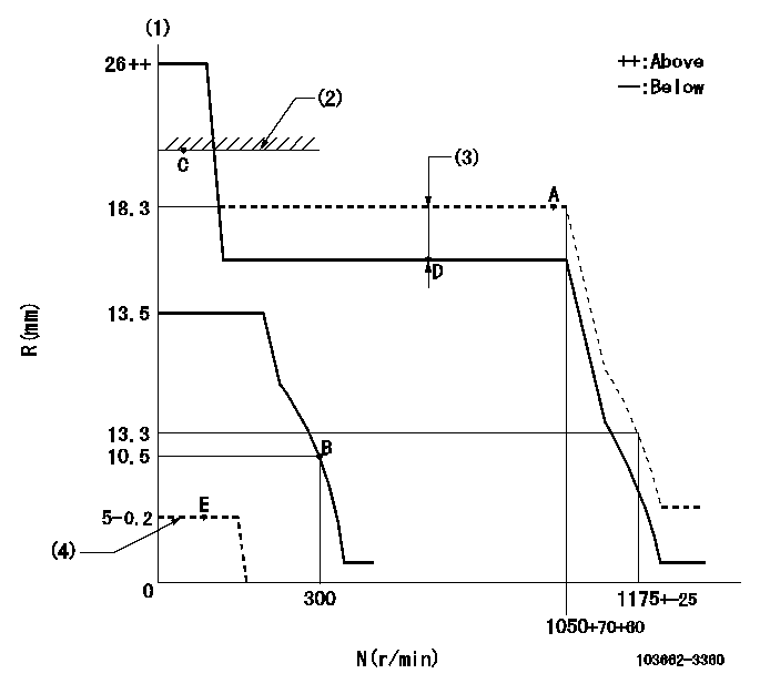
Injection quantity adjustment
Adjusting point
A
Rack position
18.3
Pump speed
r/min
1050
1050
1050
Average injection quantity
mm3/st.
499
494
504
Max. variation between cylinders
%
0
-4
4
Basic
*
Fixing the lever
*
Boost pressure
kPa
92
92
Boost pressure
mmHg
690
690
Injection quantity adjustment_02
Adjusting point
B
Rack position
10.5+-0.
5
Pump speed
r/min
300
300
300
Average injection quantity
mm3/st.
44.5
39.5
49.5
Max. variation between cylinders
%
0
-14
14
Fixing the rack
*
Boost pressure
kPa
0
0
0
Boost pressure
mmHg
0
0
0
Injection quantity adjustment_03
Adjusting point
C
Rack position
-
Pump speed
r/min
100
100
100
Average injection quantity
mm3/st.
485
485
505
Fixing the lever
*
Boost pressure
kPa
0
0
0
Boost pressure
mmHg
0
0
0
Rack limit
*
Boost compensator adjustment
Pump speed
r/min
650
650
650
Rack position
R1-4.4
Boost pressure
kPa
16
13.3
18.7
Boost pressure
mmHg
120
100
140
Boost compensator adjustment_02
Pump speed
r/min
650
650
650
Rack position
R1(18.3)
Boost pressure
kPa
78.6
71.9
85.3
Boost pressure
mmHg
590
540
640
Test data Ex:
Governor adjustment
N:Pump speed
R:Rack position (mm)
(1)Target notch: K
(2)RACK LIMIT
(3)Boost compensator stroke: BCL
(4)Stop lever at stopping (with the speed lever at full, 0 boost)
----------
K=19 BCL=4.4+-0.1mm
----------
----------
K=19 BCL=4.4+-0.1mm
----------
Speed control lever angle
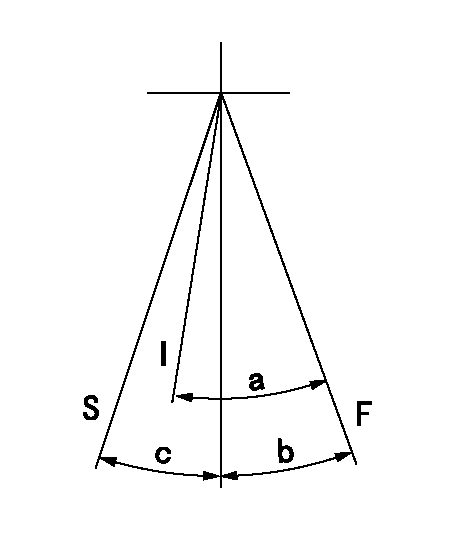
F:Full speed
I:Idle
S:Stop
----------
----------
a=37deg+-5deg b=28deg+-5deg c=30deg+-3deg
----------
----------
a=37deg+-5deg b=28deg+-5deg c=30deg+-3deg
Stop lever angle
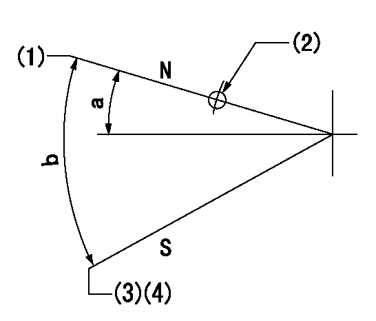
N:Pump normal
S:Stop the pump.
(1)The clearance from the set screw must be aa.
(2)Use the hole at R = bb
(3)Set the screw so that speed = cc, rack position = dd
(4)At speed lever full, 0 boost
----------
aa=2+1mm bb=40mm cc=100r/min dd=5-0.2mm
----------
a=16deg+-5deg b=40deg+-5deg
----------
aa=2+1mm bb=40mm cc=100r/min dd=5-0.2mm
----------
a=16deg+-5deg b=40deg+-5deg
Timing setting

(1)Pump vertical direction
(2)Coupling's key groove position at No 1 cylinder's beginning of injection
(3)-
(4)-
----------
----------
a=(70deg)
----------
----------
a=(70deg)