
Rating:
Information injection-pump assembly
ZEXEL
101901-0930
1019010930
ISUZU
1156008570
1156008570
Service parts 101901-0930 INJECTION-PUMP ASSEMBLY:
1.
_
2.
FUEL INJECTION PUMP
3.
GOVERNOR
4.
SUPPLY PUMP
7.
COUPLING PLATE
8.
_
9.
_
11.
Nozzle and Holder
12.
Open Pre:MPa(Kqf/cm2)
22.1(225)
13.
NOZZLE-HOLDER
14.
NOZZLE
15.
NOZZLE SET
Cross reference number
ZEXEL
101901-0930
1019010930
ISUZU
1156008570
1156008570
Zexel num
Bosch num
Firm num
Name
101901-0930
1156008570 ISUZU
INJECTION-PUMP ASSEMBLY
8PB1 * K
8PB1 * K
Calibration Data:
Adjustment conditions
Test oil
1404 Test oil ISO4113 or {SAEJ967d}
1404 Test oil ISO4113 or {SAEJ967d}
Test oil temperature
degC
40
40
45
Nozzle and nozzle holder
105780-8140
Bosch type code
EF8511/9A
Nozzle
105780-0000
Bosch type code
DN12SD12T
Nozzle holder
105780-2080
Bosch type code
EF8511/9
Opening pressure
MPa
17.2
Opening pressure
kgf/cm2
175
Injection pipe
Outer diameter - inner diameter - length (mm) mm 6-2-600
Outer diameter - inner diameter - length (mm) mm 6-2-600
Overflow valve
134424-0020
Overflow valve opening pressure
kPa
157
123
191
Overflow valve opening pressure
kgf/cm2
1.6
1.25
1.95
Tester oil delivery pressure
kPa
157
157
157
Tester oil delivery pressure
kgf/cm2
1.6
1.6
1.6
Direction of rotation (viewed from drive side)
Right R
Right R
Injection timing adjustment
Direction of rotation (viewed from drive side)
Right R
Right R
Injection order
R: right hand row, L: left hand row L1-R8-L7 -L3-R6-L 5-R4-R2
R: right hand row, L: left hand row L1-R8-L7 -L3-R6-L 5-R4-R2
Pre-stroke
mm
3.2
3.15
3.25
Beginning of injection position
Opposite to the driving side NO.1
Opposite to the driving side NO.1
Difference between angles 1
Cal 1-8 deg. 45 44.5 45.5
Cal 1-8 deg. 45 44.5 45.5
Difference between angles 2
Cal 1-7 deg. 90 89.5 90.5
Cal 1-7 deg. 90 89.5 90.5
Difference between angles 3
Cal 1-3 deg. 135 134.5 135.5
Cal 1-3 deg. 135 134.5 135.5
Difference between angles 4
Cal 1-6 deg. 180 179.5 180.5
Cal 1-6 deg. 180 179.5 180.5
Difference between angles 5
Cal 1-5 deg. 225 224.5 225.5
Cal 1-5 deg. 225 224.5 225.5
Difference between angles 6
Cal 1-4 deg. 270 269.5 270.5
Cal 1-4 deg. 270 269.5 270.5
Difference between angles 7
Cyl.1-2 deg. 315 314.5 315.5
Cyl.1-2 deg. 315 314.5 315.5
Injection quantity adjustment
Adjusting point
A
Rack position
11.7
Pump speed
r/min
1350
1350
1350
Average injection quantity
mm3/st.
90
88
92
Max. variation between cylinders
%
0
-4
4
Fixing the lever
*
Injection quantity adjustment_02
Adjusting point
B
Rack position
11.7
Pump speed
r/min
1300
1300
1300
Average injection quantity
mm3/st.
90.4
88.4
92.4
Max. variation between cylinders
%
0
-4
4
Fixing the lever
*
Injection quantity adjustment_03
Adjusting point
C
Rack position
11.7
Pump speed
r/min
700
700
700
Average injection quantity
mm3/st.
84
83
85
Max. variation between cylinders
%
0
-2
2
Basic
*
Fixing the lever
*
Injection quantity adjustment_04
Adjusting point
D
Rack position
8+-0.5
Pump speed
r/min
225
225
225
Average injection quantity
mm3/st.
8
6.7
9.3
Max. variation between cylinders
%
0
-13
13
Fixing the rack
*
Remarks
Adjust only variation between cylinders; adjust governor according to governor specifications.
Adjust only variation between cylinders; adjust governor according to governor specifications.
Injection quantity adjustment_05
Adjusting point
E
Rack position
15+-0.5
Pump speed
r/min
150
150
150
Each cylinder's injection qty
mm3/st.
95
95
Fixing the lever
*
Remarks
After startup boost setting
After startup boost setting
Timer adjustment
Pump speed
r/min
1050+-50
Advance angle
deg.
0
0
0
Remarks
Start
Start
Timer adjustment_02
Pump speed
r/min
1150
Advance angle
deg.
1.4
0.9
1.9
Timer adjustment_03
Pump speed
r/min
1250
Advance angle
deg.
3
2.5
3.5
Timer adjustment_04
Pump speed
r/min
1350
Advance angle
deg.
5
4.5
5.5
Remarks
Finish
Finish
Test data Ex:
Governor adjustment
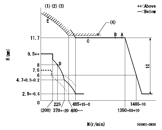
N:Pump speed
R:Rack position (mm)
(1)Beginning of damper spring operation: DL
(2)Deliver with rack limit not operating
(3)Set the load control lever's stop position so that R = aa (N = 0).
(4)Excess fuel setting for starting: SXL
----------
DL=6-0.5mm aa=7.5mm SXL=12.4+0.2mm
----------
----------
DL=6-0.5mm aa=7.5mm SXL=12.4+0.2mm
----------
0000000901
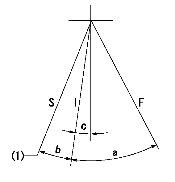
F:Full load
I:Idle
S:Stop
(1)Rack position aa (pump speed bb r/min )
----------
aa=7.5mm bb=0r/min
----------
a=32deg+-3deg b=13deg+-5deg c=1.5deg+-5deg
----------
aa=7.5mm bb=0r/min
----------
a=32deg+-3deg b=13deg+-5deg c=1.5deg+-5deg
Stop lever angle
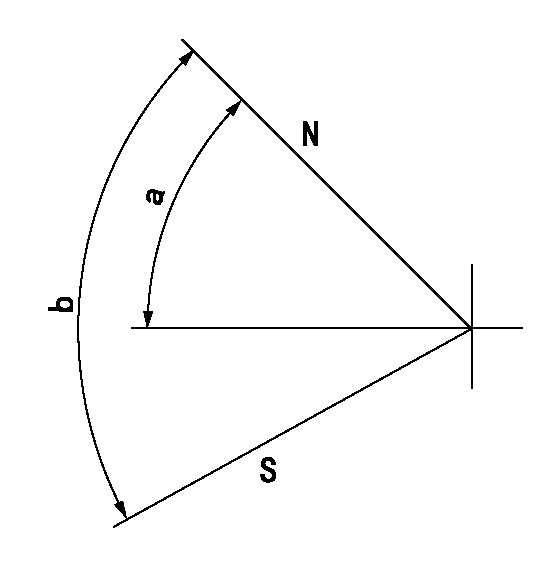
N:Pump normal
S:Stop the pump.
----------
----------
a=40deg+-5deg b=71deg+-5deg
----------
----------
a=40deg+-5deg b=71deg+-5deg
Timing setting
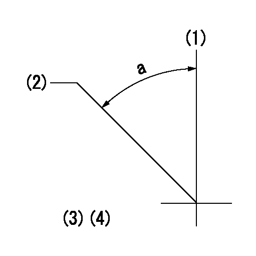
(1)Pump vertical direction
(2)Position of timer coupling's threaded installation hole at No 1 cylinder's beginning of injection
(3)B.T.D.C.: aa
(4)-
----------
aa=17deg
----------
a=(50deg)
----------
aa=17deg
----------
a=(50deg)
Have questions with 101901-0930?
Group cross 101901-0930 ZEXEL
Isuzu
101901-0930
1156008570
INJECTION-PUMP ASSEMBLY
8PB1
8PB1