
Rating:
Information injection-pump assembly
BOSCH
9 400 615 565
9400615565
ZEXEL
101606-9450
1016069450
NISSAN-DIESEL
16790Z5601
16790z5601
Service parts 101606-9450 INJECTION-PUMP ASSEMBLY:
1.
_
6.
COUPLING PLATE
7.
COUPLING PLATE
8.
_
9.
_
11.
Nozzle and Holder
16600-Z5511
12.
Open Pre:MPa(Kqf/cm2)
19.6{200}
15.
NOZZLE SET
Cross reference number
BOSCH
9 400 615 565
9400615565
ZEXEL
101606-9450
1016069450
NISSAN-DIESEL
16790Z5601
16790z5601
Zexel num
Bosch num
Firm num
Name
101606-9450
9 400 615 565
16790Z5601 NISSAN-DIESEL
INJECTION-PUMP ASSEMBLY
FD606 K 14BE INJECTION PUMP ASSY PE6A PE
FD606 K 14BE INJECTION PUMP ASSY PE6A PE
Calibration Data:
Adjustment conditions
Test oil
1404 Test oil ISO4113 or {SAEJ967d}
1404 Test oil ISO4113 or {SAEJ967d}
Test oil temperature
degC
40
40
45
Nozzle and nozzle holder
105780-8140
Bosch type code
EF8511/9A
Nozzle
105780-0000
Bosch type code
DN12SD12T
Nozzle holder
105780-2080
Bosch type code
EF8511/9
Opening pressure
MPa
17.2
Opening pressure
kgf/cm2
175
Injection pipe
Outer diameter - inner diameter - length (mm) mm 6-2-600
Outer diameter - inner diameter - length (mm) mm 6-2-600
Overflow valve
131424-1520
Overflow valve opening pressure
kPa
157
123
191
Overflow valve opening pressure
kgf/cm2
1.6
1.25
1.95
Tester oil delivery pressure
kPa
157
157
157
Tester oil delivery pressure
kgf/cm2
1.6
1.6
1.6
Direction of rotation (viewed from drive side)
Right R
Right R
Injection timing adjustment
Direction of rotation (viewed from drive side)
Right R
Right R
Injection order
1-4-2-6-
3-5
Pre-stroke
mm
3
2.95
3.05
Beginning of injection position
Drive side NO.1
Drive side NO.1
Difference between angles 1
Cal 1-4 deg. 60 59.5 60.5
Cal 1-4 deg. 60 59.5 60.5
Difference between angles 2
Cyl.1-2 deg. 120 119.5 120.5
Cyl.1-2 deg. 120 119.5 120.5
Difference between angles 3
Cal 1-6 deg. 180 179.5 180.5
Cal 1-6 deg. 180 179.5 180.5
Difference between angles 4
Cal 1-3 deg. 240 239.5 240.5
Cal 1-3 deg. 240 239.5 240.5
Difference between angles 5
Cal 1-5 deg. 300 299.5 300.5
Cal 1-5 deg. 300 299.5 300.5
Injection quantity adjustment
Adjusting point
A
Rack position
9.2
Pump speed
r/min
1350
1350
1350
Average injection quantity
mm3/st.
62
61
63
Max. variation between cylinders
%
0
-2.5
2.5
Basic
*
Fixing the lever
*
Injection quantity adjustment_02
Adjusting point
B
Rack position
7.5+-0.5
Pump speed
r/min
300
300
300
Average injection quantity
mm3/st.
8.2
7.2
9.2
Max. variation between cylinders
%
0
-12
12
Fixing the rack
*
Injection quantity adjustment_03
Adjusting point
C
Rack position
12+-0.1
Pump speed
r/min
100
100
100
Average injection quantity
mm3/st.
71
61
81
Fixing the lever
*
Rack limit
*
Timer adjustment
Pump speed
r/min
1250--
Advance angle
deg.
0
0
0
Remarks
Start
Start
Timer adjustment_02
Pump speed
r/min
1200
Advance angle
deg.
0.5
Timer adjustment_03
Pump speed
r/min
1400
Advance angle
deg.
2.5
2
3
Remarks
Finish
Finish
Test data Ex:
Governor adjustment
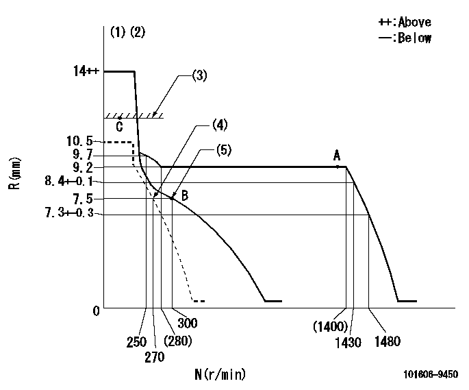
N:Pump speed
R:Rack position (mm)
(1)Target notch: K
(2)Tolerance for racks not indicated: +-0.05mm.
(3)RACK LIMIT: RAL
(4)Set idle sub-spring
(5)Main spring setting
----------
K=18 RAL=12+-0.1mm
----------
----------
K=18 RAL=12+-0.1mm
----------
Speed control lever angle
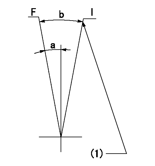
F:Full speed
I:Idle
(1)Stopper bolt setting
----------
----------
a=22deg+-5deg b=23deg+-5deg
----------
----------
a=22deg+-5deg b=23deg+-5deg
Stop lever angle
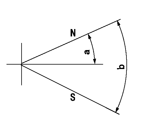
N:Pump normal
S:Stop the pump.
----------
----------
a=19deg+-5deg b=53deg+-5deg
----------
----------
a=19deg+-5deg b=53deg+-5deg
0000001501 GOV FULL LOAD ADJUSTMENT
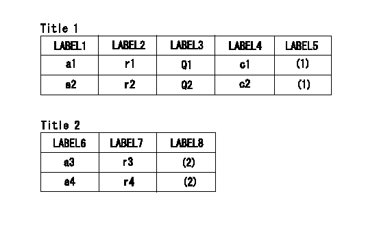
Title1:Full load stopper adjustment
Title2:Governor set speed
LABEL1:Distinguishing
LABEL2:Pump speed (r/min)
LABEL3:Ave. injection quantity (mm3/st)
LABEL4:Max. var. bet. cyl.
LABEL5:Remarks
LABEL6:Distinguishing
LABEL7:Governor set speed (r/min)
LABEL8:Remarks
(1)Adjustment conditions are the same as those for measuring injection quantity.
(2)-
----------
----------
a1=M a2=F r1=1350r/min r2=1350r/min Q1=62+-1mm3/st Q2=54+-1mm3/st c1=+-2.5% c2=+-2.5% a3=M a4=F r3=1400r/min r4=1350r/min
----------
----------
a1=M a2=F r1=1350r/min r2=1350r/min Q1=62+-1mm3/st Q2=54+-1mm3/st c1=+-2.5% c2=+-2.5% a3=M a4=F r3=1400r/min r4=1350r/min
Timing setting

(1)Pump vertical direction
(2)Position of gear mark 'G' at No 1 cylinder's beginning of injection
(3)B.T.D.C.: aa
(4)-
----------
aa=15deg
----------
a=(60deg)
----------
aa=15deg
----------
a=(60deg)
Have questions with 101606-9450?
Group cross 101606-9450 ZEXEL
Nissan-Diesel
Hyundai
Nissan-Diesel
101606-9450
9 400 615 565
16790Z5601
INJECTION-PUMP ASSEMBLY
FD606
FD606