
Rating:
Information injection-pump assembly
BOSCH
F 019 Z10 979
f019z10979
ZEXEL
101602-5091
1016025091
HINO
220206390B
220206390b
Service parts 101602-5091 INJECTION-PUMP ASSEMBLY:
1.
_
5.
AUTOM. ADVANCE MECHANIS
8.
_
9.
_
11.
Nozzle and Holder
12.
Open Pre:MPa(Kqf/cm2)
16.7(170)/21.6(220)
14.
NOZZLE
Cross reference number
BOSCH
F 019 Z10 979
f019z10979
ZEXEL
101602-5091
1016025091
HINO
220206390B
220206390b
Zexel num
Bosch num
Firm num
Name
101602-5091
F 019 Z10 979
220206390B HINO
INJECTION-PUMP ASSEMBLY
J08C-TI K 14BN INJECTION PUMP ASSY PE
J08C-TI K 14BN INJECTION PUMP ASSY PE
101602-5091
F 019 Z10 979
22100E0010 HINO
INJECTION-PUMP ASSEMBLY
J08C-TI A K 14BN INJECTION PUMP ASSY PE
J08C-TI A K 14BN INJECTION PUMP ASSY PE
Calibration Data:
Adjustment conditions
Test oil
1404 Test oil ISO4113 or {SAEJ967d}
1404 Test oil ISO4113 or {SAEJ967d}
Test oil temperature
degC
40
40
45
Nozzle and nozzle holder
105780-8140
Bosch type code
EF8511/9A
Nozzle
105780-0000
Bosch type code
DN12SD12T
Nozzle holder
105780-2080
Bosch type code
EF8511/9
Opening pressure
MPa
17.2
Opening pressure
kgf/cm2
175
Injection pipe
Outer diameter - inner diameter - length (mm) mm 6-2-600
Outer diameter - inner diameter - length (mm) mm 6-2-600
Overflow valve
131425-0620
Overflow valve opening pressure
kPa
255
221
289
Overflow valve opening pressure
kgf/cm2
2.6
2.25
2.95
Tester oil delivery pressure
kPa
255
255
255
Tester oil delivery pressure
kgf/cm2
2.6
2.6
2.6
Direction of rotation (viewed from drive side)
Left L
Left L
Injection timing adjustment
Direction of rotation (viewed from drive side)
Left L
Left L
Injection order
1-4-2-6-
3-5
Pre-stroke
mm
3.8
3.77
3.83
Beginning of injection position
Governor side NO.1
Governor side NO.1
Difference between angles 1
Cal 1-4 deg. 60 59.75 60.25
Cal 1-4 deg. 60 59.75 60.25
Difference between angles 2
Cyl.1-2 deg. 120 119.75 120.25
Cyl.1-2 deg. 120 119.75 120.25
Difference between angles 3
Cal 1-6 deg. 180 179.75 180.25
Cal 1-6 deg. 180 179.75 180.25
Difference between angles 4
Cal 1-3 deg. 240 239.75 240.25
Cal 1-3 deg. 240 239.75 240.25
Difference between angles 5
Cal 1-5 deg. 300 299.75 300.25
Cal 1-5 deg. 300 299.75 300.25
Injection quantity adjustment
Adjusting point
A
Rack position
10.8
Pump speed
r/min
700
700
700
Average injection quantity
mm3/st.
155
153
157
Max. variation between cylinders
%
0
-3.5
3.5
Basic
*
Fixing the lever
*
Boost pressure
kPa
36
36
Boost pressure
mmHg
270
270
Injection quantity adjustment_02
Adjusting point
-
Rack position
6.3+-0.5
Pump speed
r/min
390
390
390
Average injection quantity
mm3/st.
8
7
9
Max. variation between cylinders
%
0
-10
10
Fixing the rack
*
Boost pressure
kPa
0
0
0
Boost pressure
mmHg
0
0
0
Remarks
Adjust only variation between cylinders; adjust governor according to governor specifications.
Adjust only variation between cylinders; adjust governor according to governor specifications.
Injection quantity adjustment_03
Adjusting point
E
Rack position
11.2++
Pump speed
r/min
100
100
100
Average injection quantity
mm3/st.
150
150
160
Fixing the lever
*
Boost pressure
kPa
0
0
0
Boost pressure
mmHg
0
0
0
Rack limit
*
Boost compensator adjustment
Pump speed
r/min
700
700
700
Rack position
9.5
Boost pressure
kPa
9.3
8
10.6
Boost pressure
mmHg
70
60
80
Boost compensator adjustment_02
Pump speed
r/min
700
700
700
Rack position
10.8
Boost pressure
kPa
22.7
16
29.4
Boost pressure
mmHg
170
120
220
Test data Ex:
Governor adjustment
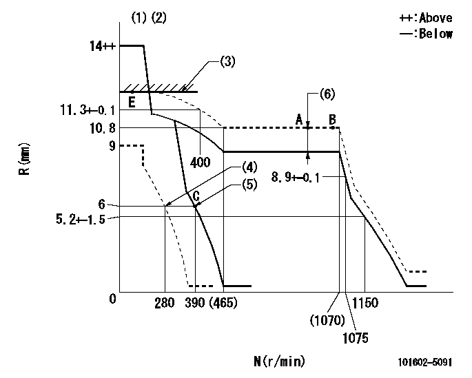
N:Pump speed
R:Rack position (mm)
(1)Notch fixed: K
(2)Tolerance for racks not indicated: +-0.05mm.
(3)RACK LIMIT
(4)Set idle sub-spring
(5)Main spring setting
(6)Boost compensator stroke: BCL
----------
K=16 BCL=1.3+-0.1mm
----------
----------
K=16 BCL=1.3+-0.1mm
----------
Speed control lever angle
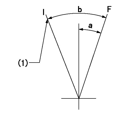
F:Full speed
I:Idle
(1)Stopper bolt setting
----------
----------
a=(11deg)+-5deg b=(28deg)+-5deg
----------
----------
a=(11deg)+-5deg b=(28deg)+-5deg
Stop lever angle
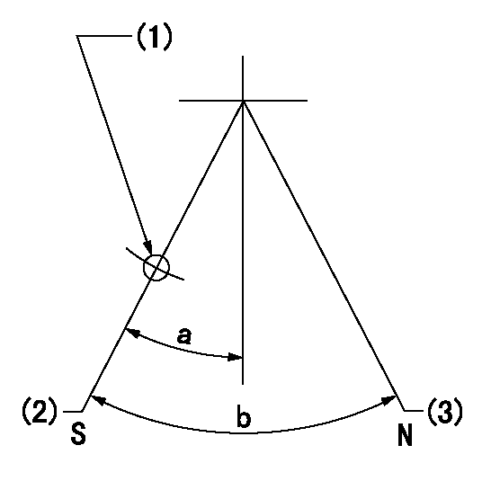
N:Pump normal
S:Stop the pump.
(1)Use the hole at R = aa
(2)Rack position bb, pump speed cc (seal at delivery)
(3)Normal
----------
aa=25mm bb=2-0.5mm cc=0r/min
----------
a=19deg+-5deg b=(53deg)
----------
aa=25mm bb=2-0.5mm cc=0r/min
----------
a=19deg+-5deg b=(53deg)
Timing setting
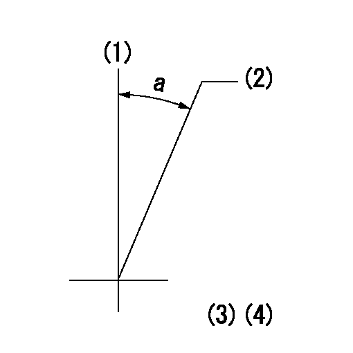
(1)Pump vertical direction
(2)Coupling's key groove position at No 1 cylinder's beginning of injection
(3)-
(4)-
----------
----------
a=(20deg)
----------
----------
a=(20deg)
Have questions with 101602-5091?
Group cross 101602-5091 ZEXEL
Hino
101602-5091
F 019 Z10 979
220206390B
INJECTION-PUMP ASSEMBLY
J08C-TI
J08C-TI
101602-5091
F 019 Z10 979
22100E0010
INJECTION-PUMP ASSEMBLY
J08C-TI
J08C-TI