Rating:
Information injection-pump assembly
BOSCH
9 400 611 276
9400611276
ZEXEL
106682-1010
1066821010
ISUZU
1156032530
1156032530
Service parts 106682-1010 INJECTION-PUMP ASSEMBLY:
1.
_
5.
AUTOM. ADVANCE MECHANIS
7.
COUPLING PLATE
8.
_
11.
Nozzle and Holder
1-15300-366-0
12.
Open Pre:MPa(Kqf/cm2)
22.1{225}
15.
NOZZLE SET
Include in #1:
106682-1010
as INJECTION-PUMP ASSEMBLY
Cross reference number
BOSCH
9 400 611 276
9400611276
ZEXEL
106682-1010
1066821010
ISUZU
1156032530
1156032530
Zexel num
Bosch num
Firm num
Name
106682-1010
9 400 611 276
1156032530 ISUZU
INJECTION-PUMP ASSEMBLY
6SD1-MTC K 14CA INJECTION PUMP ASSY PE6P,6PD PE
6SD1-MTC K 14CA INJECTION PUMP ASSY PE6P,6PD PE
Calibration Data:
Adjustment conditions
Test oil
1404 Test oil ISO4113 or {SAEJ967d}
1404 Test oil ISO4113 or {SAEJ967d}
Test oil temperature
degC
40
40
45
Nozzle and nozzle holder
105780-8250
Bosch type code
1 688 901 101
Nozzle
105780-0120
Bosch type code
1 688 901 990
Nozzle holder
105780-2190
Opening pressure
MPa
20.7
Opening pressure
kgf/cm2
211
Injection pipe
Outer diameter - inner diameter - length (mm) mm 8-3-600
Outer diameter - inner diameter - length (mm) mm 8-3-600
Overflow valve
134424-1920
Overflow valve opening pressure
kPa
127
107
147
Overflow valve opening pressure
kgf/cm2
1.3
1.1
1.5
Tester oil delivery pressure
kPa
255
255
255
Tester oil delivery pressure
kgf/cm2
2.6
2.6
2.6
Direction of rotation (viewed from drive side)
Left L
Left L
Injection timing adjustment
Direction of rotation (viewed from drive side)
Left L
Left L
Injection order
1-5-3-6-
2-4
Pre-stroke
mm
3.2
3.17
3.23
Beginning of injection position
Governor side NO.1
Governor side NO.1
Difference between angles 1
Cal 1-5 deg. 60 59.75 60.25
Cal 1-5 deg. 60 59.75 60.25
Difference between angles 2
Cal 1-3 deg. 120 119.75 120.25
Cal 1-3 deg. 120 119.75 120.25
Difference between angles 3
Cal 1-6 deg. 180 179.75 180.25
Cal 1-6 deg. 180 179.75 180.25
Difference between angles 4
Cyl.1-2 deg. 240 239.75 240.25
Cyl.1-2 deg. 240 239.75 240.25
Difference between angles 5
Cal 1-4 deg. 300 299.75 300.25
Cal 1-4 deg. 300 299.75 300.25
Injection quantity adjustment
Adjusting point
A
Rack position
13.7
Pump speed
r/min
1200
1200
1200
Average injection quantity
mm3/st.
176
174
178
Max. variation between cylinders
%
0
-2.5
2.5
Basic
*
Fixing the lever
*
Boost pressure
kPa
213
213
Boost pressure
mmHg
1600
1600
Injection quantity adjustment_02
Adjusting point
Z
Rack position
7.1+-0.5
Pump speed
r/min
340
340
340
Average injection quantity
mm3/st.
14
12
16
Max. variation between cylinders
%
0
-14
14
Fixing the rack
*
Boost pressure
kPa
0
0
0
Boost pressure
mmHg
0
0
0
Injection quantity adjustment_03
Adjusting point
D
Rack position
R1(12.25
)
Pump speed
r/min
500
500
500
Average injection quantity
mm3/st.
219
214
224
Fixing the lever
*
Boost pressure
kPa
0
0
0
Boost pressure
mmHg
0
0
0
Injection quantity adjustment_04
Adjusting point
E
Rack position
-
Pump speed
r/min
100
100
100
Average injection quantity
mm3/st.
230
230
270
Fixing the lever
*
Boost pressure
kPa
0
0
0
Boost pressure
mmHg
0
0
0
Boost compensator adjustment
Pump speed
r/min
650
650
650
Rack position
R1(12.25
)
Boost pressure
kPa
156
153.3
158.7
Boost pressure
mmHg
1170
1150
1190
Boost compensator adjustment_02
Pump speed
r/min
650
650
650
Rack position
(13.7)
Boost pressure
kPa
200
200
200
Boost pressure
mmHg
1500
1500
1500
Test data Ex:
Governor adjustment
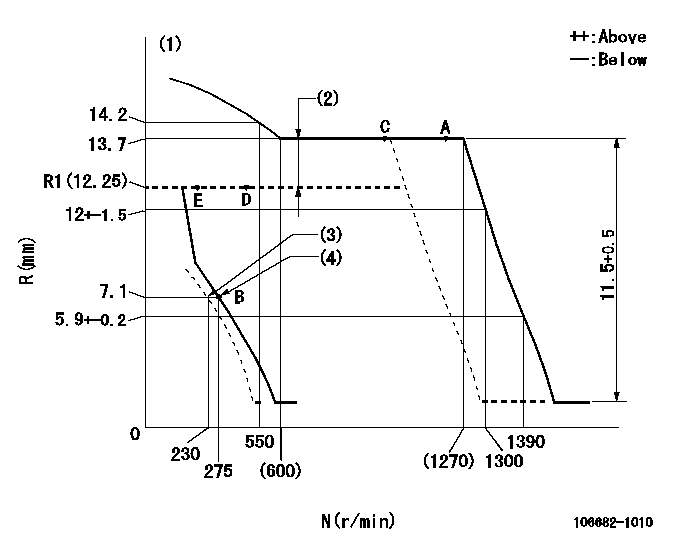
N:Pump speed
R:Rack position (mm)
(1)Tolerance for racks not indicated: +-0.05mm.
(2)Boost compensator stroke: BCL
(3)Set idle sub-spring (with the lever free).
(4)Main spring setting
----------
BCL=(1.45)+-0.1mm
----------
----------
BCL=(1.45)+-0.1mm
----------
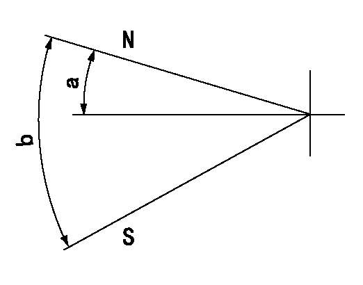
Speed control lever angle
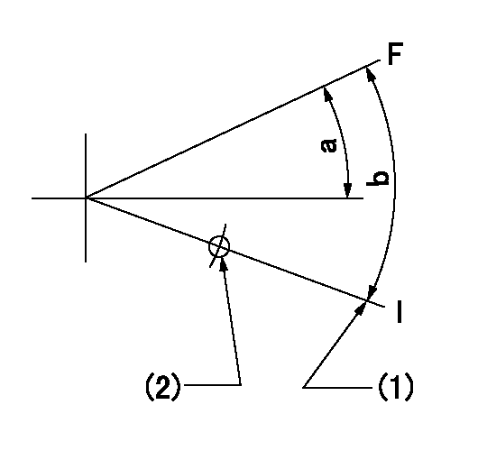
F:Full speed
I:Idle
(1)Stopper bolt setting
(2)Pull at right angles to the hole at R = aa
----------
aa=135mm
----------
a=(9deg)+-5deg b=(19deg)+-5deg
----------
aa=135mm
----------
a=(9deg)+-5deg b=(19deg)+-5deg
0000000901
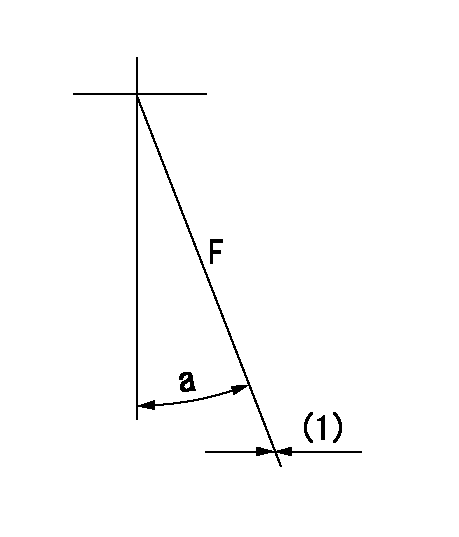
F:Full load
(1)Fix using the stopper bolt.
----------
----------
a=15deg+-5deg
----------
----------
a=15deg+-5deg
Stop lever angle
N:Pump normal
S:Stop the pump.
----------
----------
a=28deg+-5deg b=71deg+-5deg
----------
----------
a=28deg+-5deg b=71deg+-5deg
Timing setting

(1)Pump vertical direction
(2)Position of damper's threaded hole at No 1 cylinder's beginning of injection
(3)B.T.D.C.: aa
(4)-
----------
aa=19deg
----------
a=(8deg)
----------
aa=19deg
----------
a=(8deg)
Have questions with 106682-1010?
Group cross 106682-1010 ZEXEL
Isuzu
106682-1010
9 400 611 276
1156032530
INJECTION-PUMP ASSEMBLY
6SD1-MTC
6SD1-MTC