
Rating:
Information injection-pump assembly
ZEXEL
106671-6250
1066716250
ISUZU
1156032130
1156032130
Service parts 106671-6250 INJECTION-PUMP ASSEMBLY:
1.
_
7.
COUPLING PLATE
8.
_
9.
_
11.
Nozzle and Holder
1-15300-332-0
12.
Open Pre:MPa(Kqf/cm2)
17.7{180}/22.1{225}
 BASCOLIN Original Nozzles DLLA152SM070 105025-0700 9 432 611 546")
15.
NOZZLE SET
Include in #1:
106671-6250
as INJECTION-PUMP ASSEMBLY
Cross reference number
ZEXEL
106671-6250
1066716250
ISUZU
1156032130
1156032130
Zexel num
Bosch num
Firm num
Name
Calibration Data:
Adjustment conditions
Test oil
1404 Test oil ISO4113 or {SAEJ967d}
1404 Test oil ISO4113 or {SAEJ967d}
Test oil temperature
degC
40
40
45
Nozzle and nozzle holder
105780-8140
Bosch type code
EF8511/9A
Nozzle
105780-0000
Bosch type code
DN12SD12T
Nozzle holder
105780-2080
Bosch type code
EF8511/9
Opening pressure
MPa
17.2
Opening pressure
kgf/cm2
175
Injection pipe
Outer diameter - inner diameter - length (mm) mm 8-3-600
Outer diameter - inner diameter - length (mm) mm 8-3-600
Overflow valve
131424-8620
Overflow valve opening pressure
kPa
206
172
240
Overflow valve opening pressure
kgf/cm2
2.1
1.75
2.45
Tester oil delivery pressure
kPa
157
157
157
Tester oil delivery pressure
kgf/cm2
1.6
1.6
1.6
Direction of rotation (viewed from drive side)
Left L
Left L
Injection timing adjustment
Direction of rotation (viewed from drive side)
Left L
Left L
Injection order
1-5-3-6-
2-4
Pre-stroke
mm
4.5
4.47
4.53
Beginning of injection position
Governor side NO.1
Governor side NO.1
Difference between angles 1
Cal 1-5 deg. 60 59.75 60.25
Cal 1-5 deg. 60 59.75 60.25
Difference between angles 2
Cal 1-3 deg. 120 119.75 120.25
Cal 1-3 deg. 120 119.75 120.25
Difference between angles 3
Cal 1-6 deg. 180 179.75 180.25
Cal 1-6 deg. 180 179.75 180.25
Difference between angles 4
Cyl.1-2 deg. 240 239.75 240.25
Cyl.1-2 deg. 240 239.75 240.25
Difference between angles 5
Cal 1-4 deg. 300 299.75 300.25
Cal 1-4 deg. 300 299.75 300.25
Injection quantity adjustment
Adjusting point
-
Rack position
11.7
Pump speed
r/min
800
800
800
Average injection quantity
mm3/st.
155.5
153.5
157.5
Max. variation between cylinders
%
0
-3
3
Basic
*
Fixing the rack
*
Standard for adjustment of the maximum variation between cylinders
*
Injection quantity adjustment_02
Adjusting point
H
Rack position
6.4+-0.5
Pump speed
r/min
290
290
290
Average injection quantity
mm3/st.
10
6.8
13.2
Max. variation between cylinders
%
0
-13
13
Fixing the rack
*
Standard for adjustment of the maximum variation between cylinders
*
Injection quantity adjustment_03
Adjusting point
A
Rack position
R1(11.7)
Pump speed
r/min
800
800
800
Average injection quantity
mm3/st.
155.5
153.5
157.5
Basic
*
Fixing the lever
*
Boost pressure
kPa
60
60
Boost pressure
mmHg
450
450
Injection quantity adjustment_04
Adjusting point
B
Rack position
R1+0.45
Pump speed
r/min
1100
1100
1100
Average injection quantity
mm3/st.
158
152
164
Fixing the lever
*
Boost pressure
kPa
60
60
Boost pressure
mmHg
450
450
Boost compensator adjustment
Pump speed
r/min
500
500
500
Rack position
R2-1.75
Boost pressure
kPa
4
4
6.7
Boost pressure
mmHg
30
30
50
Boost compensator adjustment_02
Pump speed
r/min
500
500
500
Rack position
R2[R1-0.
65]
Boost pressure
kPa
46.7
46.7
46.7
Boost pressure
mmHg
350
350
350
Timer adjustment
Pump speed
r/min
850--
Advance angle
deg.
0
0
0
Remarks
Start
Start
Timer adjustment_02
Pump speed
r/min
800
Advance angle
deg.
0.5
Timer adjustment_03
Pump speed
r/min
875
Advance angle
deg.
1.5
1
2
Remarks
Finish
Finish
Test data Ex:
Governor adjustment
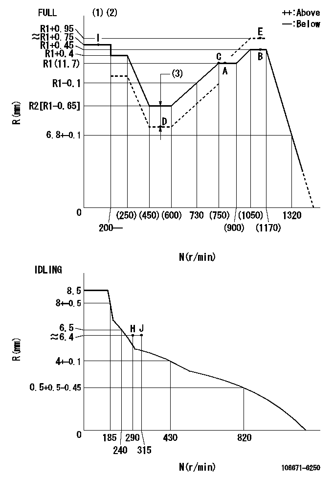
N:Pump speed
R:Rack position (mm)
(1)Torque cam stamping: T1
(2)Tolerance for racks not indicated: +-0.05mm.
(3)Boost compensator stroke: BCL
----------
T1=AE45 BCL=1.75+-0.1mm
----------
----------
T1=AE45 BCL=1.75+-0.1mm
----------
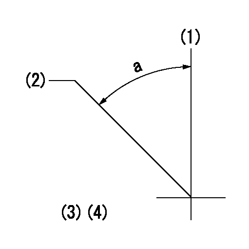
Speed control lever angle
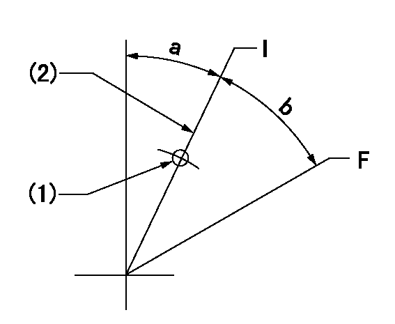
F:Full speed
I:Idle
(1)Use the pin at R = aa
(2)Stopper bolt setting
----------
aa=35mm
----------
a=27deg+-5deg b=30.5deg+-3deg
----------
aa=35mm
----------
a=27deg+-5deg b=30.5deg+-3deg
Stop lever angle
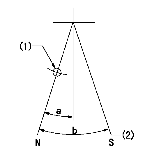
N:Pump normal
S:Stop the pump.
(1)Use the pin at R = aa
(2)Set the stopper bolt so that speed = bb and rack position = cc. (Confirm non-injection.)
----------
aa=40mm bb=0r/min cc=1.5+-0.3mm
----------
a=22deg+-5deg b=41deg+-5deg
----------
aa=40mm bb=0r/min cc=1.5+-0.3mm
----------
a=22deg+-5deg b=41deg+-5deg
0000001501 TAMPER PROOF
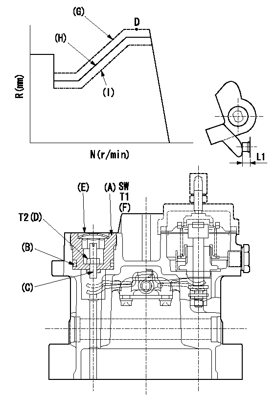
SW:Inner hexagonal SW14
(F): Apply thread lock adhesive .
(G): Full tamper proof
(H): Full boost (Full rack)
(I): 0 boost
1. Mount (C) and (D) after adjusting the boost compensator.
2. Back off the load lever set screw L1 from the end face of the governor housing..
3. Apply boost pressure and set the full load at tamper set position point aa to obtain N1, Q1 and Ra using the screw C.
4. Fix using the nut (D).
5. Next, after adjusting the stop lever, confirm the point aa.
6. Reset the load lever to the full boost rack.
7. After completion of setting, seal using the plug (E).
----------
L1=- N1=1100r/min R1=R1(11.7)+0.95mm Q=(172.5)mm3/st aa=E
----------
T1=53.9~73.5N-m(5.5~7.5Kgf-m) T2=2.94~4.41N-m(0.3~0.45Kgf-m)
----------
L1=- N1=1100r/min R1=R1(11.7)+0.95mm Q=(172.5)mm3/st aa=E
----------
T1=53.9~73.5N-m(5.5~7.5Kgf-m) T2=2.94~4.41N-m(0.3~0.45Kgf-m)
0000001601 TAMPER PROOF
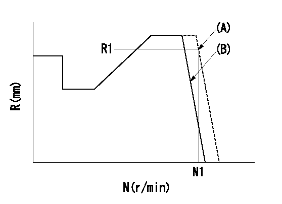
(A): Rotation tamper proof
(B): Full-speed setting
1. Back off the full-speed set bolt.
2. Confirm that the tamper setting position is N1, R1, Q1.
3. At that time, record the angle of the speed lever.
4. After confirming the above setting, set full speed.
----------
N1=1440r/min R1=(6.8)mm Q1=-
----------
----------
N1=1440r/min R1=(6.8)mm Q1=-
----------
Timing setting
(1)Pump vertical direction
(2)Position of timer's threaded hole at No 1 cylinder's beginning of injection
(3)B.T.D.C.: aa
(4)-
----------
aa=10deg
----------
a=(50deg)
----------
aa=10deg
----------
a=(50deg)