Rating:
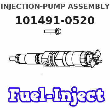
Information injection-pump assembly
ZEXEL
101491-0520
1014910520
ISUZU
8970140770
8970140770
Service parts 101491-0520 INJECTION-PUMP ASSEMBLY:
1.
_
6.
COUPLING PLATE
7.
COUPLING PLATE
8.
_
9.
_
11.
Nozzle and Holder
8-97021-703-1
12.
Open Pre:MPa(Kqf/cm2)
21.6{220}

15.
NOZZLE SET
Cross reference number
ZEXEL
101491-0520
1014910520
ISUZU
8970140770
8970140770
Zexel num
Bosch num
Firm num
Name
101491-0520
8970140770 ISUZU
INJECTION-PUMP ASSEMBLY
4BE1 * K
4BE1 * K
Calibration Data:
Adjustment conditions
Test oil
1404 Test oil ISO4113 or {SAEJ967d}
1404 Test oil ISO4113 or {SAEJ967d}
Test oil temperature
degC
40
40
45
Nozzle and nozzle holder
105780-8140
Bosch type code
EF8511/9A
Nozzle
105780-0000
Bosch type code
DN12SD12T
Nozzle holder
105780-2080
Bosch type code
EF8511/9
Opening pressure
MPa
17.2
Opening pressure
kgf/cm2
175
Injection pipe
Outer diameter - inner diameter - length (mm) mm 6-2-600
Outer diameter - inner diameter - length (mm) mm 6-2-600
Overflow valve
131424-4920
Overflow valve opening pressure
kPa
127
107
147
Overflow valve opening pressure
kgf/cm2
1.3
1.1
1.5
Tester oil delivery pressure
kPa
157
157
157
Tester oil delivery pressure
kgf/cm2
1.6
1.6
1.6
Direction of rotation (viewed from drive side)
Right R
Right R
Injection timing adjustment
Direction of rotation (viewed from drive side)
Right R
Right R
Injection order
1-3-4-2
Pre-stroke
mm
3.8
3.75
3.85
Rack position
After adjusting injection quantity. R=A
After adjusting injection quantity. R=A
Beginning of injection position
Drive side NO.1
Drive side NO.1
Difference between angles 1
Cal 1-3 deg. 90 89.5 90.5
Cal 1-3 deg. 90 89.5 90.5
Difference between angles 2
Cal 1-4 deg. 180 179.5 180.5
Cal 1-4 deg. 180 179.5 180.5
Difference between angles 3
Cyl.1-2 deg. 270 269.5 270.5
Cyl.1-2 deg. 270 269.5 270.5
Injection quantity adjustment
Adjusting point
-
Rack position
13
Pump speed
r/min
1050
1050
1050
Average injection quantity
mm3/st.
73.2
71.6
74.8
Max. variation between cylinders
%
0
-2.5
2.5
Basic
*
Fixing the rack
*
Standard for adjustment of the maximum variation between cylinders
*
Injection quantity adjustment_02
Adjusting point
H
Rack position
9.5+-0.5
Pump speed
r/min
300
300
300
Average injection quantity
mm3/st.
10.2
8.9
11.5
Max. variation between cylinders
%
0
-14
14
Fixing the rack
*
Standard for adjustment of the maximum variation between cylinders
*
Injection quantity adjustment_03
Adjusting point
A
Rack position
R1(13)
Pump speed
r/min
1050
1050
1050
Average injection quantity
mm3/st.
73.2
72.2
74.2
Basic
*
Fixing the lever
*
Injection quantity adjustment_04
Adjusting point
B
Rack position
R1-0.1
Pump speed
r/min
1750
1750
1750
Average injection quantity
mm3/st.
77.3
73.3
81.3
Fixing the lever
*
Injection quantity adjustment_05
Adjusting point
I
Rack position
-
Pump speed
r/min
100
100
100
Average injection quantity
mm3/st.
92
92
124
Fixing the lever
*
Timer adjustment
Pump speed
r/min
1550--
Advance angle
deg.
0
0
0
Remarks
Start
Start
Timer adjustment_02
Pump speed
r/min
1500
Advance angle
deg.
0.3
Timer adjustment_03
Pump speed
r/min
1800
Advance angle
deg.
4.5
4
5
Remarks
Finish
Finish
Test data Ex:
Governor adjustment
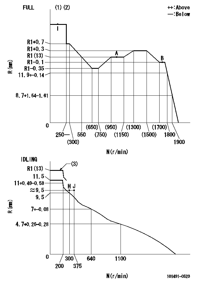
N:Pump speed
R:Rack position (mm)
(1)Torque cam stamping: T1
(2)Tolerance for racks not indicated: +-0.05mm.
(3)At delivery (at R = A, N = N1)
----------
T1=E69 N1=100r/min
----------
----------
T1=E69 N1=100r/min
----------
Speed control lever angle
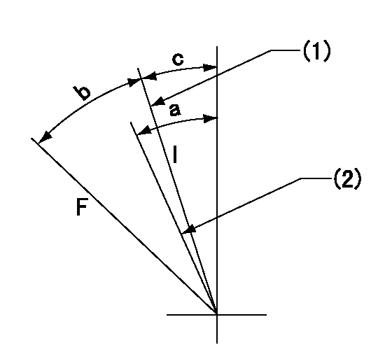
F:Full speed
I:Idle
(1)Stopper bolt set position 'H'
(2)Set the idle side stopper bolt at speed = aa and rack position = bb (at delivery)
----------
aa=100r/min bb=R1(13)mm
----------
a=(8deg) b=42deg+-3deg c=2.5deg+-5deg
----------
aa=100r/min bb=R1(13)mm
----------
a=(8deg) b=42deg+-3deg c=2.5deg+-5deg
Stop lever angle
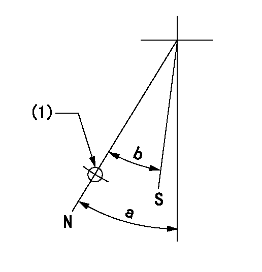
N:Pump normal
S:Stop the pump.
(1)Use the hole at R = aa
----------
aa=64mm
----------
a=45deg+-5deg b=29deg+-5deg
----------
aa=64mm
----------
a=45deg+-5deg b=29deg+-5deg
0000001501 I/P WITH LOAD PLUNGER ADJ
Plunger assembly number: PL (stamping: ST)
1. Adjustment procedures
(1)Insert the pre-stroke adjusting shims L1 for each cylinder.
(2)Adjust injection quantity.(max. var. bet. cyl. idling a1, full a2)
(3)At basic point A, adjust so that the pre-stroke is L2.
(4)Reconfirm the injection quantity.
----------
PL=131154-1820 ST=A260 L1=1mm L2=3.8+-0.05mm a1=+-14% a2=+-2.5%
----------
----------
PL=131154-1820 ST=A260 L1=1mm L2=3.8+-0.05mm a1=+-14% a2=+-2.5%
----------
Timing setting
(1)Pump vertical direction
(2)Position of gear mark 'CC' at No 1 cylinder's beginning of injection
(3)B.T.D.C.: aa
(4)-
----------
aa=15deg
----------
a=(90deg)
----------
aa=15deg
----------
a=(90deg)
Have questions with 101491-0520?
Group cross 101491-0520 ZEXEL
Isuzu
101491-0520
8970140770
INJECTION-PUMP ASSEMBLY
4BE1
4BE1