
Rating:
Information injection-pump assembly
ZEXEL
108622-1090
1086221090
ISUZU
1156032710
1156032710
Service parts 108622-1090 INJECTION-PUMP ASSEMBLY:
1.
_
5.
AUTOM. ADVANCE MECHANIS
7.
COUPLING PLATE
11.
Nozzle and Holder
1-15300-359-0
12.
Open Pre:MPa(Kqf/cm2)
17.7{180}/22.1{225}
14.
NOZZLE
Include in #1:
108622-1090
as INJECTION-PUMP ASSEMBLY
Cross reference number
ZEXEL
108622-1090
1086221090
ISUZU
1156032710
1156032710
Zexel num
Bosch num
Firm num
Name
Calibration Data:
Adjustment conditions
Test oil
1404 Test oil ISO4113 or {SAEJ967d}
1404 Test oil ISO4113 or {SAEJ967d}
Test oil temperature
degC
40
40
45
Nozzle and nozzle holder
105780-8250
Bosch type code
1 688 901 101
Nozzle
105780-0120
Bosch type code
1 688 901 990
Nozzle holder
105780-2190
Opening pressure
MPa
20.7
Opening pressure
kgf/cm2
211
Injection pipe
Outer diameter - inner diameter - length (mm) mm 8-3-600
Outer diameter - inner diameter - length (mm) mm 8-3-600
Overflow valve
131424-7120
Overflow valve opening pressure
kPa
255
221
289
Overflow valve opening pressure
kgf/cm2
2.6
2.25
2.95
Tester oil delivery pressure
kPa
255
255
255
Tester oil delivery pressure
kgf/cm2
2.6
2.6
2.6
PS/ACT control unit part no.
407980-2
24*
Digi switch no.
32
Direction of rotation (viewed from drive side)
Left L
Left L
Injection timing adjustment
Direction of rotation (viewed from drive side)
Left L
Left L
Injection order
1-5-3-6-
2-4
Pre-stroke
mm
8.5
8.47
8.53
Beginning of injection position
Governor side NO.1
Governor side NO.1
Difference between angles 1
Cal 1-5 deg. 60 59.75 60.25
Cal 1-5 deg. 60 59.75 60.25
Difference between angles 2
Cal 1-3 deg. 120 119.75 120.25
Cal 1-3 deg. 120 119.75 120.25
Difference between angles 3
Cal 1-6 deg. 180 179.75 180.25
Cal 1-6 deg. 180 179.75 180.25
Difference between angles 4
Cyl.1-2 deg. 240 239.75 240.25
Cyl.1-2 deg. 240 239.75 240.25
Difference between angles 5
Cal 1-4 deg. 300 299.75 300.25
Cal 1-4 deg. 300 299.75 300.25
Injection quantity adjustment
Adjusting point
-
Rack position
12.2
Pump speed
r/min
800
800
800
Average injection quantity
mm3/st.
146.5
144.5
148.5
Max. variation between cylinders
%
0
-3
3
Basic
*
Fixing the rack
*
PS407980-224*
V
2.45+-0.
01
PS407980-224*
mm
6.1+-0.0
5
Standard for adjustment of the maximum variation between cylinders
*
Injection quantity adjustment_02
Adjusting point
Z
Rack position
6.7+-0.5
Pump speed
r/min
355
355
355
Average injection quantity
mm3/st.
15
11.8
18.2
Max. variation between cylinders
%
0
-13
13
Fixing the rack
*
PS407980-224*
V
V1+0.05+
-0.01
PS407980-224*
mm
8.4+-0.0
3
Standard for adjustment of the maximum variation between cylinders
*
Remarks
Refer to items regarding the pre-stroke actuator
Refer to items regarding the pre-stroke actuator
Injection quantity adjustment_03
Adjusting point
A
Rack position
R1(12.2)
Pump speed
r/min
800
800
800
Average injection quantity
mm3/st.
146.5
144.5
148.5
Basic
*
Fixing the lever
*
Boost pressure
kPa
49.3
49.3
Boost pressure
mmHg
370
370
PS407980-224*
V
2.45+-0.
01
PS407980-224*
mm
6.1+-0.0
5
Boost compensator adjustment
Pump speed
r/min
530
530
530
Rack position
R2-2
Boost pressure
kPa
4
4
6.7
Boost pressure
mmHg
30
30
50
Boost compensator adjustment_02
Pump speed
r/min
530
530
530
Rack position
R2(R1-1.
25)
Boost pressure
kPa
36
36
36
Boost pressure
mmHg
270
270
270
0000001601
Pre-stroke
mm
8.5
8.47
8.5
Remarks
When the timing sleeve is pushed up
When the timing sleeve is pushed up
_02
Connector angle
deg.
8.5
8
9
Remarks
When the eccentric pin is tightened
When the eccentric pin is tightened
_03
Supply voltage
V
24
23.5
24.5
Ambient temperature
degC
23
18
28
Pre-stroke
mm
6.1
6.05
6.15
Output voltage
V
2.45
2.44
2.46
Adjustment
*
_04
Supply voltage
V
24
23.5
24.5
Ambient temperature
degC
23
18
28
Pre-stroke
mm
8.5
8.47
8.53
Output voltage
V
1.2
1
1.4
Confirmation
*
Remarks
Output voltage V1
Output voltage V1
_05
Supply voltage
V
24
23.5
24.5
Ambient temperature
degC
23
18
28
Pre-stroke
mm
5.5
Output voltage
V
3
2.98
3
Confirmation
*
_06
Supply voltage
V
24
23.5
24.5
Ambient temperature
degC
23
18
28
Output voltage
V
3.05
3.05
Confirmation of operating range
*
Test data Ex:
Governor adjustment
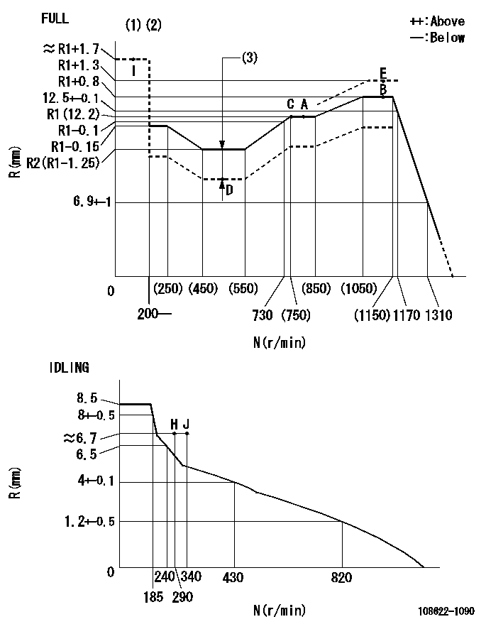
N:Pump speed
R:Rack position (mm)
(1)Torque cam stamping: T1
(2)Tolerance for racks not indicated: +-0.05mm.
(3)Boost compensator stroke: BCL
----------
T1=AE40 BCL=2+-0.1mm
----------
----------
T1=AE40 BCL=2+-0.1mm
----------
Speed control lever angle
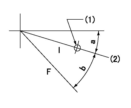
F:Full speed
I:Idle
(1)Use the hole at R = aa
(2)Stopper bolt set position 'H'
----------
aa=35mm
----------
a=20deg+-5deg b=28deg+-3deg
----------
aa=35mm
----------
a=20deg+-5deg b=28deg+-3deg
Stop lever angle
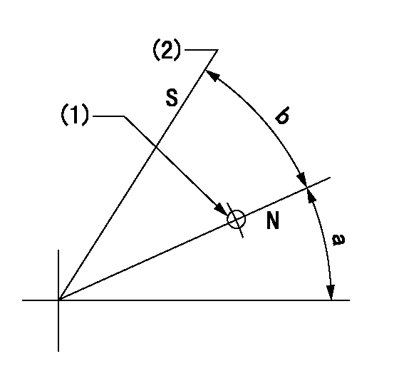
N:Pump normal
S:Stop the pump.
(1)Use the pin at R = aa
(2)At pump speed bb and rack position cc, set the stopper bolt. (Confirm non-injection.)
----------
aa=40mm bb=0r/min cc=1.5+-0.3mm
----------
a=14deg+-5deg b=41deg+-5deg
----------
aa=40mm bb=0r/min cc=1.5+-0.3mm
----------
a=14deg+-5deg b=41deg+-5deg
0000001301
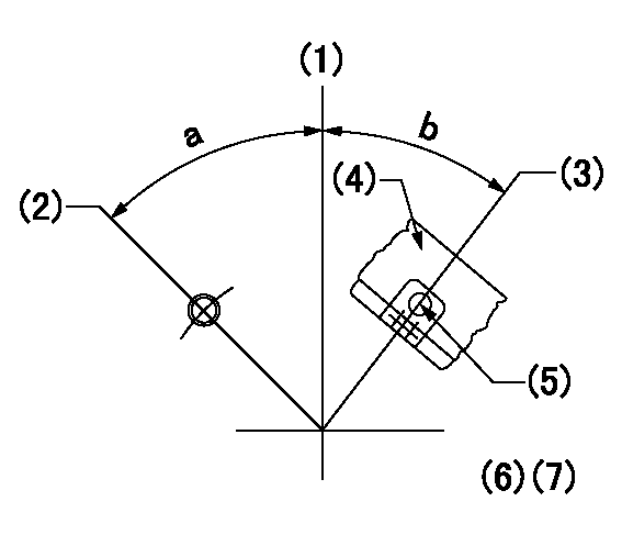
(1)Pump vertical direction
(2)Position of damper's threaded hole at No 1 cylinder's beginning of injection
(3)At the No 1 cylinder's beginning of injection position, stamp an aligning mark on the damper to align with the pointer's groove.
(4)Damper
(5)Pointer
(6)B.T.D.C.: aa
(7)Pre-stroke: bb
----------
aa=5deg bb=8.5+-0.03mm
----------
a=(50deg) b=(44deg)
----------
aa=5deg bb=8.5+-0.03mm
----------
a=(50deg) b=(44deg)
0000001901
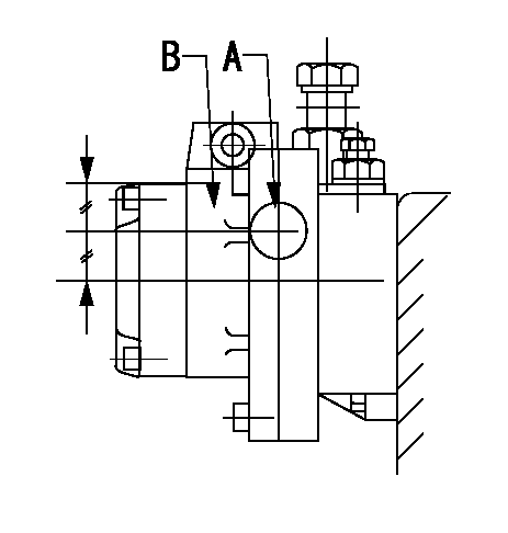
A:Sealing position
B:Pre-stroke actuator
1. When installing the pre-stroke actuator on the pump, first tighten the installation bolts loosely, then move the actuator fully counterclockwise (viewed from the drive side).
Temporary tightening torque: 1 - 1.5 N.m (0.1 - 0.15 kgf.m)
2. Move the actuator in the clockwise direction when viewed from the drive side, and adjust so that it becomes the adjustment point of the adjustment value. Then tighten it.
Tightening torque: 7^9 N.m (0.7^0.9 kgf.m)
3. After prestroke actuator installation adjustment, simultaneously stamp both the actuator side and housing side.
----------
----------
----------
----------
0000002201 TAMPER PROOF
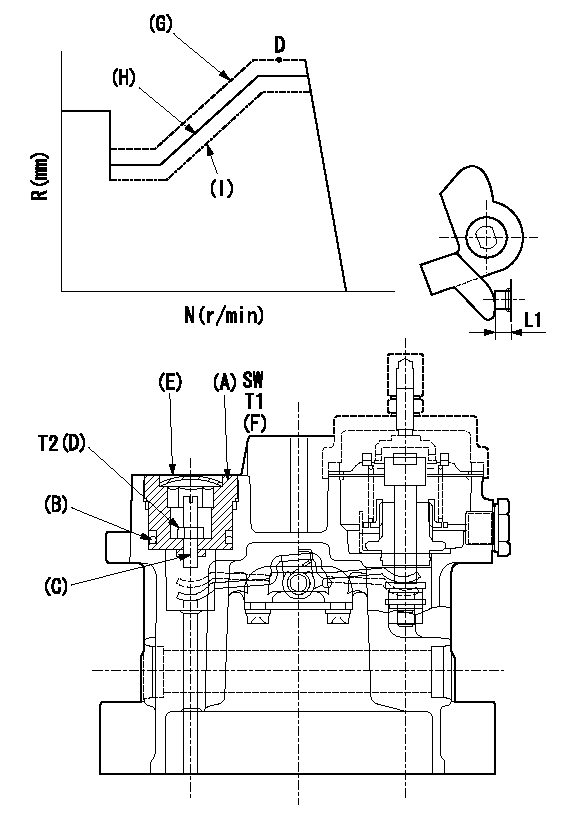
SW:Inner hexagonal SW14
(F): Apply thread lock adhesive .
(G): Full tamper proof
(H): Full boost (Full rack)
(I): 0 boost
1. Mount (C) and (D) after adjusting the boost compensator.
2. Back off the load lever set screw L1 from the end face of the governor housing..
3. Apply boost pressure and set the full load at tamper set position point aa to obtain N1, Q1 and Ra using the screw C.
4. Fix using the nut (D).
5. Next, after adjusting the stop lever, confirm the point aa.
6. Reset the load lever to the full boost rack.
7. After completion of setting, seal using the plug (E).
----------
L1=6+1mm N1=1100r/min Q1=(154.5)mm3/1000st Ra=R1+1.3mm aa=E
----------
T1 T=53.9~73.5N-m(5.5~7.5Kgf-m) T2 T=2.94~4.41N-m(0.3~0.45Kgf-m)
----------
L1=6+1mm N1=1100r/min Q1=(154.5)mm3/1000st Ra=R1+1.3mm aa=E
----------
T1 T=53.9~73.5N-m(5.5~7.5Kgf-m) T2 T=2.94~4.41N-m(0.3~0.45Kgf-m)
0000002301 TAMPER PROOF
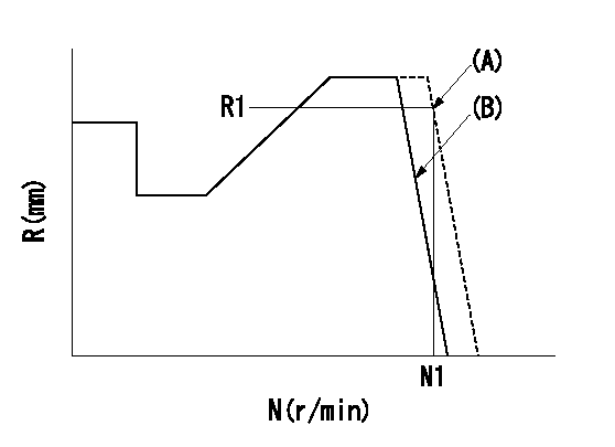
(A): Rotation tamper proof
(B): Full-speed setting
1. Back off the full-speed set bolt.
2. Confirm that the tamper setting position is N1, R1, Q1.
3. At that time, record the angle of the speed lever.
4. After confirming the above setting, set full speed.
----------
N1=1360r/min R1=(6.9)mm Q1=-
----------
----------
N1=1360r/min R1=(6.9)mm Q1=-
----------
0000002401 RACK SENSOR
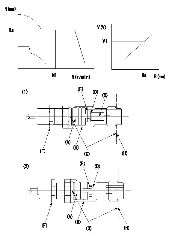
G:Red paint
H:Pump end face
P/N: part number of suitable shim
(1)Threaded type rack block
(2)Welded type rack block
Rack sensor adjustment
1. Threaded type rack sensor (-5*20, P type, no TICS rack limit).
(1)Screw in the bobbin (A) until it contacts the joint (B).
(2)Fix the pump lever.
(3)At speed N1 and rack position Ra, adjust the amount that the bobbin is screwed in so that the amp's output voltage is V1.
(4)Fix using the nut (F).
(5)Affix the caution plate to the upper part of the joint (B).
(6)Apply (G) at two places.
Connecting part between the joint (B) and the nut (F)
Connecting part between the end surface of the pump (H) and the joint (B)
2. Range for screw-in adjustment between the bobbin (A) and the joint (B) is 9 threads.
Screw in to the end from (the position where the bobbin (A) is rotated 9 turns).
Speed N1, rack position Ra, output voltage V1, rack sensor supply voltage 5+-0.01 (V)
----------
Ra=R1(12.2)+0.8mm N1=1100r/min V1=3+-0.01V
----------
----------
Ra=R1(12.2)+0.8mm N1=1100r/min V1=3+-0.01V
----------