
Rating:
Information injection-pump assembly
BOSCH
F 019 Z10 220
f019z10220
ZEXEL
107491-3050
1074913050
HINO
220008401A
220008401a
Service parts 107491-3050 INJECTION-PUMP ASSEMBLY:
1.
_
6.
COUPLING PLATE
7.
COUPLING PLATE
9.
_
11.
Nozzle and Holder
12.
Open Pre:MPa(Kqf/cm2)
21.6{220}
15.
NOZZLE SET
Include in #1:
107491-3050
as INJECTION-PUMP ASSEMBLY
Cross reference number
BOSCH
F 019 Z10 220
f019z10220
ZEXEL
107491-3050
1074913050
HINO
220008401A
220008401a
Zexel num
Bosch num
Firm num
Name
Calibration Data:
Adjustment conditions
Test oil
1404 Test oil ISO4113 or {SAEJ967d}
1404 Test oil ISO4113 or {SAEJ967d}
Test oil temperature
degC
40
40
45
Nozzle and nozzle holder
105780-8250
Bosch type code
1 688 901 101
Nozzle
105780-0120
Bosch type code
1 688 901 990
Nozzle holder
105780-2190
Opening pressure
MPa
20.7
Opening pressure
kgf/cm2
211
Injection pipe
Outer diameter - inner diameter - length (mm) mm 8-3-600
Outer diameter - inner diameter - length (mm) mm 8-3-600
Overflow valve
131424-9720
Overflow valve opening pressure
kPa
255
221
289
Overflow valve opening pressure
kgf/cm2
2.6
2.25
2.95
Tester oil delivery pressure
kPa
255
255
255
Tester oil delivery pressure
kgf/cm2
2.6
2.6
2.6
PS/ACT control unit part no.
407910-3
03*
Selector switch no.
02
PS/ACT control unit part no.
407980-2
24*
Digi switch no.
01
Direction of rotation (viewed from drive side)
Right R
Right R
Injection timing adjustment
Direction of rotation (viewed from drive side)
Right R
Right R
Injection order
1-3-4-2
Pre-stroke
mm
5.1
5.07
5.13
Beginning of injection position
Drive side NO.1
Drive side NO.1
Difference between angles 1
Cal 1-3 deg. 90 89.75 90.25
Cal 1-3 deg. 90 89.75 90.25
Difference between angles 2
Cal 1-4 deg. 180 179.75 180.25
Cal 1-4 deg. 180 179.75 180.25
Difference between angles 3
Cyl.1-2 deg. 270 269.75 270.25
Cyl.1-2 deg. 270 269.75 270.25
Injection quantity adjustment
Adjusting point
-
Rack position
11.5
Pump speed
r/min
900
900
900
Average injection quantity
mm3/st.
111
109
113
Max. variation between cylinders
%
0
-3
3
Basic
*
Fixing the rack
*
PS407980-224*
V
2.25+-0.
01
PS407980-224*
mm
3.1+-0.0
5
PS407910-303*
V
2.25+-0.
01
PS407910-303*
mm
3.1+-0.0
5
Standard for adjustment of the maximum variation between cylinders
*
Injection quantity adjustment_02
Adjusting point
Z
Rack position
6+-0.5
Pump speed
r/min
430
430
430
Average injection quantity
mm3/st.
19.5
18
21
Max. variation between cylinders
%
0
-15
15
Fixing the rack
*
PS407980-224*
V
V1+0.05+
-0.01
PS407980-224*
mm
5+-0.03
PS407910-303*
V
V1+0.05+
-0.01
PS407910-303*
mm
5+-0.03
Standard for adjustment of the maximum variation between cylinders
*
Remarks
Refer to items regarding the pre-stroke actuator
Refer to items regarding the pre-stroke actuator
Injection quantity adjustment_03
Adjusting point
A
Rack position
R1(11.5)
Pump speed
r/min
900
900
900
Average injection quantity
mm3/st.
111
110
112
Basic
*
Fixing the lever
*
Boost pressure
kPa
62.7
62.7
Boost pressure
mmHg
470
470
PS407980-224*
V
2.25+-0.
01
PS407980-224*
mm
3.1+-0.0
5
PS407910-303*
V
2.25+-0.
01
PS407910-303*
mm
3.1+-0.0
5
Injection quantity adjustment_04
Adjusting point
B
Rack position
R1+1.25
Pump speed
r/min
1400
1400
1400
Average injection quantity
mm3/st.
108
104
112
Fixing the lever
*
Boost pressure
kPa
62.7
62.7
Boost pressure
mmHg
470
470
PS407980-224*
V
2.25+-0.
01
PS407980-224*
mm
3.1+-0.0
5
PS407910-303*
V
2.25+-0.
01
PS407910-303*
mm
3.1+-0.0
5
Injection quantity adjustment_05
Adjusting point
C
Rack position
(R2-1.3)
Pump speed
r/min
400
400
400
Average injection quantity
mm3/st.
55.5
53.5
57.5
Fixing the lever
*
Boost pressure
kPa
0
0
0
Boost pressure
mmHg
0
0
0
PS407980-224*
V
2.25+-0.
01
PS407980-224*
mm
3.1+-0.0
5
PS407910-303*
V
2.25+-0.
01
PS407910-303*
mm
3.1+-0.0
5
Boost compensator adjustment
Pump speed
r/min
400
400
400
Rack position
(R2-1.3)
Boost pressure
kPa
29.3
28
30.6
Boost pressure
mmHg
220
210
230
Boost compensator adjustment_02
Pump speed
r/min
400
400
400
Rack position
R2(R1-2.
2)
Boost pressure
kPa
49.3
49.3
49.3
Boost pressure
mmHg
370
370
370
Timer adjustment
Pump speed
r/min
1150--
Advance angle
deg.
0
0
0
Remarks
Start
Start
Timer adjustment_02
Pump speed
r/min
1100
Advance angle
deg.
0
-0.3
0
Timer adjustment_03
Pump speed
r/min
1350-50
Advance angle
deg.
-1.5
-1.8
-1.2
Remarks
Finish
Finish
0000001601
CU407980-224*
*
Actuator retarding type
*
Supply voltage
V
12
11.5
12.5
Ambient temperature
degC
23
18
28
Pre-stroke
mm
2
1.95
2.05
Output voltage
V
2.83
2.82
2.84
Adjustment
*
_02
CU407980-224*
*
Supply voltage
V
12
11.5
12.5
Ambient temperature
degC
23
18
28
Pre-stroke
mm
5.1
5.07
5.13
Output voltage
V
1.2
1
1.4
Confirmation
*
Remarks
Output voltage V1
Output voltage V1
_03
CU407980-224*
*
Supply voltage
V
12
11.5
12.5
Ambient temperature
degC
23
18
28
Output voltage
V
3.05
3.05
Confirmation of operating range
*
_04
CU407910-303*
*
Actuator retarding type
*
Supply voltage
V
12
11.5
12.5
Ambient temperature
degC
23
18
28
Pre-stroke
mm
2
1.95
2.05
Output voltage
V
2.83
2.82
2.84
Adjustment
*
_05
CU407910-303*
*
Supply voltage
V
12
11.5
12.5
Ambient temperature
degC
23
18
28
Pre-stroke
mm
5.1
5.07
5.13
Output voltage
V
1.2
1
1.4
Confirmation
*
Remarks
Output voltage V1
Output voltage V1
_06
CU407910-303*
*
Supply voltage
V
12
11.5
12.5
Ambient temperature
degC
23
18
28
Output voltage
V
3.05
3.05
Confirmation of operating range
*
Test data Ex:
Governor adjustment
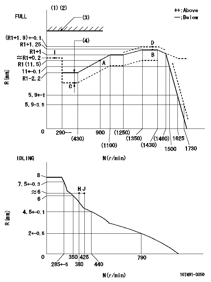
N:Pump speed
R:Rack position (mm)
(1)Torque cam stamping: T1
(2)Tolerance for racks not indicated: +-0.05mm.
(3)Stop lever's normal position setting: R1
(4)Boost compensator stroke: BCL
----------
T1=AB76 R1=(16.5)mm BCL=(1.3)+-0.1mm
----------
----------
T1=AB76 R1=(16.5)mm BCL=(1.3)+-0.1mm
----------
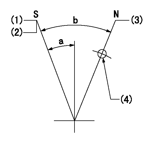
Speed control lever angle
F:Full speed
I:Idle
(1)Use the hole at R = aa
(2)Stopper bolt set position 'H'
----------
aa=51mm
----------
a=(33.5deg)+-3deg b=40.5deg+-5deg
----------
aa=51mm
----------
a=(33.5deg)+-3deg b=40.5deg+-5deg
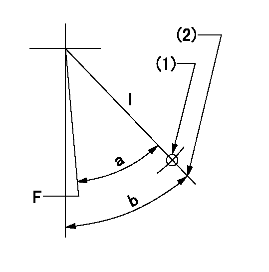
Stop lever angle
N:Pump normal
S:Stop the pump.
(1)Pump speed aa, rack position bb
(2)(Confirm non-injection at speed = cc.)
(3)Rack position = dd
(4)Use the hole above R = ee
----------
aa=0r/min bb=0.5+-0.3mm cc=1625r/min dd=(16.5)mm ee=40mm
----------
a=17deg+-5deg b=34deg+-5deg
----------
aa=0r/min bb=0.5+-0.3mm cc=1625r/min dd=(16.5)mm ee=40mm
----------
a=17deg+-5deg b=34deg+-5deg
0000001301
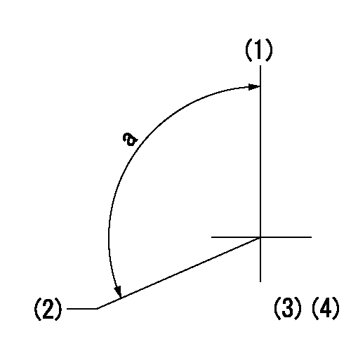
(1)Pump vertical direction
(2)Position of gear's standard threaded hole at No 1 cylinder's beginning of injection
(3)Pre-stroke: aa
(4)-
----------
aa=5.1+-0.03mm
----------
a=(120deg)
----------
aa=5.1+-0.03mm
----------
a=(120deg)
0000001401
(1)Pointer
(2)Injection timing aligning mark
(3)Fly weight
(4)The actual shape and direction may be different from this illustration.
Operation sequence
1. Turn the prestroke actuator OFF.
2. Turn the camshaft as far as the No.1 cylinder's beginning of injection position.
3. Check that the pointer alignment mark of the injection pump and the alignment mark of the flywheel are matching.
4. If they are not matching, erase the alignment mark on the flywheel side, and stamp an alignment mark on the flywheel position that matches with the pointer side alignment mark.
5. Check again that the coupling's key groove position is in the No.1 cylinder's beginning of injection position.
----------
----------
----------
----------
0000001701
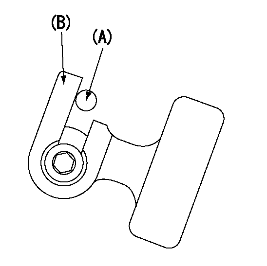
A : Stopper pin
B: Connector
----------
----------
----------
----------
0000001801
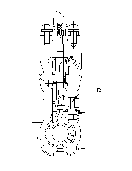
C:Shim
----------
----------
----------
----------
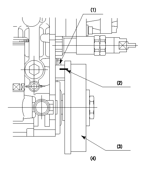
0000001901
A:Sealing position
B:Pre-stroke actuator
1. When installing the pre-stroke actuator on the pump, first tighten the installation bolts loosely, then move the actuator fully counterclockwise (viewed from the drive side).
Temporary tightening torque: 1 - 1.5 N.m (0.1 - 0.15 kgf.m)
2. Move the actuator in the clockwise direction when viewed from the drive side, and adjust so that it becomes the adjustment point of the adjustment value. Then tighten it.
Tightening torque: 7^9 N.m (0.7^0.9 kgf.m)
3. After prestroke actuator installation adjustment, simultaneously stamp both the actuator side and housing side.
----------
----------
----------
----------
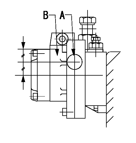
0000002201 TAMPER PROOF
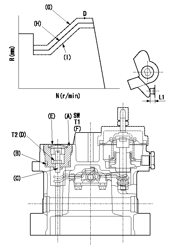
SW:Inner hexagonal SW14
(F): Apply thread lock adhesive .
(G): Full tamper proof
(H): Full boost (Full rack)
(I): 0 boost
1. Mount (C) and (D) after adjusting the boost compensator.
2. Back off the load lever set screw L1 from the end face of the governor housing..
3. Apply boost pressure and set the full load at tamper set position point aa to obtain N1, Q1 and Ra using the screw C.
4. Fix using the nut (D).
5. Next, after adjusting the stop lever, confirm the point aa.
6. Reset the load lever to the full boost rack.
7. After completion of setting, seal using the plug (E).
----------
L1=6+1mm N1=1400r/min Q1=- Ra=(R1+1.9)+-0.1mm aa=D
----------
T1 T=53.9~73.5N-m(5.5~7.5Kgf-m) T2 T=2.94~4.41N-m(0.3~0.45Kgf-m)
----------
L1=6+1mm N1=1400r/min Q1=- Ra=(R1+1.9)+-0.1mm aa=D
----------
T1 T=53.9~73.5N-m(5.5~7.5Kgf-m) T2 T=2.94~4.41N-m(0.3~0.45Kgf-m)
0000002301 TAMPER PROOF
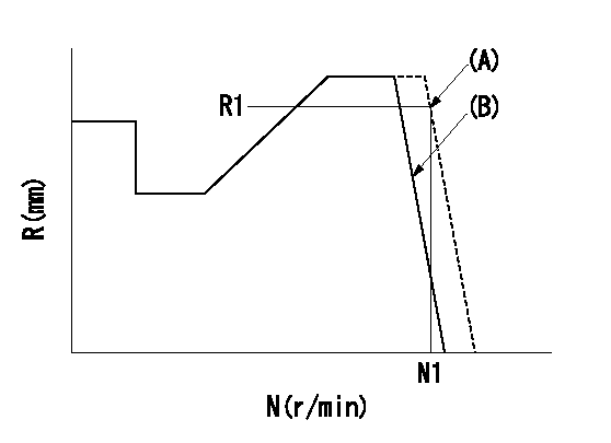
(A): Rotation tamper proof
(B): Full-speed setting
1. Back off the full-speed set bolt.
2. Confirm that the tamper setting position is N1, R1, Q1.
3. At that time, record the angle of the speed lever.
4. After confirming the above setting, set full speed.
----------
N1=1730r/min R1=5.9-3.5mm Q1=-
----------
----------
N1=1730r/min R1=5.9-3.5mm Q1=-
----------
0000002401 RACK SENSOR
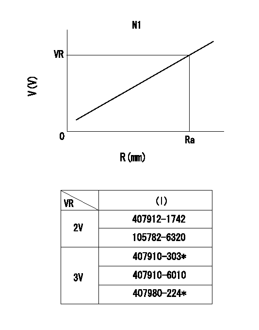
R:Rack position (mm)
V:Voltage (V)
After installing the rack sensor, confirm the output value (VR).
----------
N1=1400r/min Ra=R1(11.5)+1.25mm VR=2.06+-0.13V(for 2V C/U) VR=3.05+-0.1V(for 3V C/U)
----------
----------
N1=1400r/min Ra=R1(11.5)+1.25mm VR=2.06+-0.13V(for 2V C/U) VR=3.05+-0.1V(for 3V C/U)
----------