
Rating:
Information injection-pump assembly
ZEXEL
106971-3201
1069713201
HINO
220008881A
220008881a
Service parts 106971-3201 INJECTION-PUMP ASSEMBLY:
1.
_
7.
COUPLING PLATE
8.
_
9.
_
11.
Nozzle and Holder
23600-2750A
12.
Open Pre:MPa(Kqf/cm2)
14.7{150}/21.6{220}
14.
NOZZLE
Include in #1:
106971-3201
as INJECTION-PUMP ASSEMBLY
Cross reference number
ZEXEL
106971-3201
1069713201
HINO
220008881A
220008881a
Zexel num
Bosch num
Firm num
Name
Calibration Data:
Adjustment conditions
Test oil
1404 Test oil ISO4113 or {SAEJ967d}
1404 Test oil ISO4113 or {SAEJ967d}
Test oil temperature
degC
40
40
45
Nozzle and nozzle holder
105780-8250
Bosch type code
1 688 901 101
Nozzle
105780-0120
Bosch type code
1 688 901 990
Nozzle holder
105780-2190
Opening pressure
MPa
20.7
Opening pressure
kgf/cm2
211
Injection pipe
Outer diameter - inner diameter - length (mm) mm 8-3-600
Outer diameter - inner diameter - length (mm) mm 8-3-600
Overflow valve
134424-4120
Overflow valve opening pressure
kPa
255
221
289
Overflow valve opening pressure
kgf/cm2
2.6
2.25
2.95
Tester oil delivery pressure
kPa
255
255
255
Tester oil delivery pressure
kgf/cm2
2.6
2.6
2.6
Direction of rotation (viewed from drive side)
Right R
Right R
Injection timing adjustment
Direction of rotation (viewed from drive side)
Right R
Right R
Injection order
1-10-9-4
-3-6-5-8
-7-2
Pre-stroke
mm
4.2
4.14
4.2
Beginning of injection position
Governor side NO.1
Governor side NO.1
Difference between angles 1
Cal 1-10 deg. 27 26.75 27.25
Cal 1-10 deg. 27 26.75 27.25
Difference between angles 2
Cal 1-9 deg. 72 71.75 72.25
Cal 1-9 deg. 72 71.75 72.25
Difference between angles 3
Cal 1-4 deg. 99 98.75 99.25
Cal 1-4 deg. 99 98.75 99.25
Difference between angles 4
Cal 1-3 deg. 144 143.75 144.25
Cal 1-3 deg. 144 143.75 144.25
Difference between angles 5
Cal 1-6 deg. 171 170.75 171.25
Cal 1-6 deg. 171 170.75 171.25
Difference between angles 6
Cal 1-5 deg. 216 215.75 216.25
Cal 1-5 deg. 216 215.75 216.25
Difference between angles 7
Cal 1-8 deg. 243 242.75 243.25
Cal 1-8 deg. 243 242.75 243.25
Difference between angles 8
Cal 1-7 deg. 288 287.75 288.25
Cal 1-7 deg. 288 287.75 288.25
Difference between angles 9
Cyl.1-2 deg. 315 314.75 315.25
Cyl.1-2 deg. 315 314.75 315.25
Injection quantity adjustment
Adjusting point
-
Rack position
12.3
Pump speed
r/min
700
700
700
Average injection quantity
mm3/st.
127.5
124.5
130.5
Max. variation between cylinders
%
0
-4
4
Basic
*
Fixing the rack
*
Standard for adjustment of the maximum variation between cylinders
*
Injection quantity adjustment_02
Adjusting point
Z
Rack position
8+-0.5
Pump speed
r/min
455
455
455
Average injection quantity
mm3/st.
15
12
18
Max. variation between cylinders
%
0
-10
10
Fixing the rack
*
Standard for adjustment of the maximum variation between cylinders
*
Injection quantity adjustment_03
Adjusting point
A
Rack position
R1(12.3)
Pump speed
r/min
700
700
700
Average injection quantity
mm3/st.
127.5
125.5
129.5
Basic
*
Fixing the lever
*
Injection quantity adjustment_04
Adjusting point
B
Rack position
R1+0.25
Pump speed
r/min
1100
1100
1100
Average injection quantity
mm3/st.
113
110
116
Fixing the lever
*
Timer adjustment
Pump speed
r/min
720--
Advance angle
deg.
0
0
0
Load
2/5
Remarks
Start
Start
Timer adjustment_02
Pump speed
r/min
670
Advance angle
deg.
0.3
Load
2/5
Timer adjustment_03
Pump speed
r/min
(790--)
Advance angle
deg.
2
1.7
2.3
Load
5/5
Timer adjustment_04
Pump speed
r/min
890
Advance angle
deg.
2
1.7
2.3
Load
4/5
Timer adjustment_05
Pump speed
r/min
(960--)
Advance angle
deg.
2
1.7
2.3
Load
5/5
Timer adjustment_06
Pump speed
r/min
1080-50
Advance angle
deg.
6.75
6.45
7.05
Load
5/5
Remarks
Finish
Finish
Test data Ex:
Governor adjustment
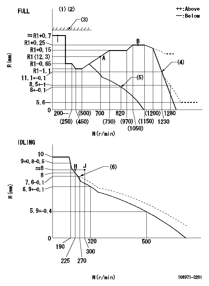
N:Pump speed
R:Rack position (mm)
(1)Torque cam stamping: T1
(2)Tolerance for racks not indicated: +-0.05mm.
(3)Stop lever's normal position setting: equivalent to RA
(4)Air cylinder ON
(5)Air cylinder OFF
(6)Damper spring setting
----------
T1=AD08 RA=18mm
----------
----------
T1=AD08 RA=18mm
----------
Speed control lever angle
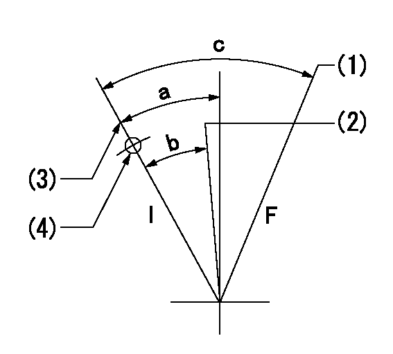
F:Full speed
I:Idle
(1)When air cylinder ON.
(2)When air cylinder OFF.
(3)Stopper bolt set position 'H'
(4)Use the hole at R = aa
----------
aa=47mm
----------
a=20deg+-5deg b=(12deg) c=33deg+-3deg
----------
aa=47mm
----------
a=20deg+-5deg b=(12deg) c=33deg+-3deg
Stop lever angle
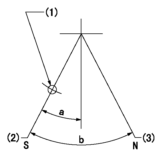
N:Pump normal
S:Stop the pump.
(1)Use the pin at R = aa
(2)Set the stopper bolt so that speed = bb and rack position = cc. (Confirm non-injection.)
(3)Set the stopper bolt so that rack position = dd.
----------
aa=40mm bb=0r/min cc=4+-0.3mm dd=18mm
----------
a=8.5deg+-5deg b=30deg+-5deg
----------
aa=40mm bb=0r/min cc=4+-0.3mm dd=18mm
----------
a=8.5deg+-5deg b=30deg+-5deg
0000001501 LEVER
Stop lever setting
When setting the stop lever after governor adjustment, confirm that rack position Ra can be obtained at full setting.
----------
Ra=R1(12.3)+0.7mm
----------
----------
Ra=R1(12.3)+0.7mm
----------
0000001601 AIR CYLINDER
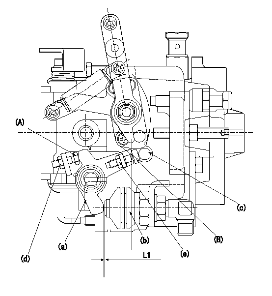
(A) stopper bolt
(B) stopper bolt
(C) stopper bolt
(a) lever
(b) air cylinder
(c) speed lever
(d) Nut
(e) nut
1. Stopper bolt A adjusting method
(1)When air cylinder pressure is P1, set the gap between the lever (a) and the air cylinder (b) to L1.
(2)Apply P2 to the air cylinder.
(3)Confirm that the speed lever (c) operates between idling and full speed positions.
(4)Fix the stopper bolt A using nut d.
2. Stopper bolt <B> adjustment method.
(1)At air cylinder pressure P1, pump speed N1 and rack position is Ra, adjust stopper bolt (B) so that the speed lever (c) is in the stop position.
(2)Move the lever a several times and then fix the stopper bolt B using the nut e.
(3)Nut d tightening torque: T1
(4)Nut e tightening torque: T2
----------
L1=(1)mm P1=0kPa(0kgf/cm2) P2=392+98kPa(4+1kgf/cm2) N1=820r/min Ra=8+0.1mm T1=4.9~7N-m(0.5~0.7kgf-m) T2=4.9~7N-m(0.5~0.7kgf-m)
----------
----------
L1=(1)mm P1=0kPa(0kgf/cm2) P2=392+98kPa(4+1kgf/cm2) N1=820r/min Ra=8+0.1mm T1=4.9~7N-m(0.5~0.7kgf-m) T2=4.9~7N-m(0.5~0.7kgf-m)
----------
Timing setting
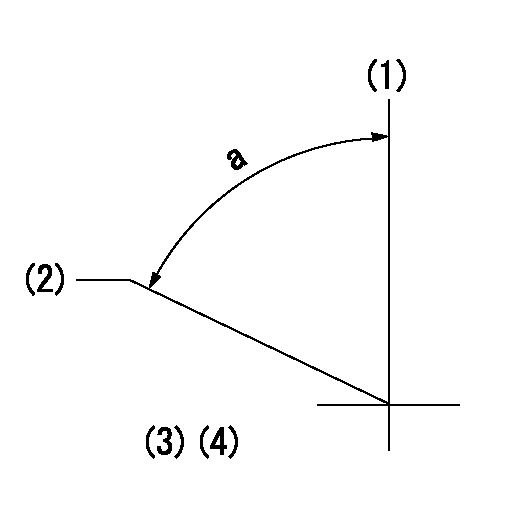
(1)Pump vertical direction
(2)Coupling's key groove position at No 1 cylinder's beginning of injection
(3)-
(4)-
----------
----------
a=(80deg)
----------
----------
a=(80deg)