
Rating:
Information injection-pump assembly
ZEXEL
106971-0520
1069710520
NISSAN-DIESEL
1680097004
1680097004
Cross reference number
ZEXEL
106971-0520
1069710520
NISSAN-DIESEL
1680097004
1680097004
Zexel num
Bosch num
Firm num
Name
Calibration Data:
Adjustment conditions
Test oil
1404 Test oil ISO4113 or {SAEJ967d}
1404 Test oil ISO4113 or {SAEJ967d}
Test oil temperature
degC
40
40
45
Nozzle and nozzle holder
105780-8140
Bosch type code
EF8511/9A
Nozzle
105780-0000
Bosch type code
DN12SD12T
Nozzle holder
105780-2080
Bosch type code
EF8511/9
Opening pressure
MPa
17.2
Opening pressure
kgf/cm2
175
Injection pipe
Outer diameter - inner diameter - length (mm) mm 8-3-600
Outer diameter - inner diameter - length (mm) mm 8-3-600
Overflow valve
132424-0620
Overflow valve opening pressure
kPa
157
123
191
Overflow valve opening pressure
kgf/cm2
1.6
1.25
1.95
Tester oil delivery pressure
kPa
157
157
157
Tester oil delivery pressure
kgf/cm2
1.6
1.6
1.6
Direction of rotation (viewed from drive side)
Right R
Right R
Injection timing adjustment
Direction of rotation (viewed from drive side)
Right R
Right R
Injection order
10-9-4-3
-6-5-8-7
-2-1
Pre-stroke
mm
3.65
3.6
3.7
Beginning of injection position
Governor side NO.1
Governor side NO.1
Difference between angles 1
Cal 10-9 deg. 45 44.5 45.5
Cal 10-9 deg. 45 44.5 45.5
Difference between angles 2
Cal 10-4 deg. 72 71.5 72.5
Cal 10-4 deg. 72 71.5 72.5
Difference between angles 3
Cal 10-3 deg. 117 116.5 117.5
Cal 10-3 deg. 117 116.5 117.5
Difference between angles 4
Cal 10-6 deg. 144 143.5 144.5
Cal 10-6 deg. 144 143.5 144.5
Difference between angles 5
Cal 10-5 deg. 189 188.5 189.5
Cal 10-5 deg. 189 188.5 189.5
Difference between angles 6
Cal 10-8 deg. 216 215.5 216.5
Cal 10-8 deg. 216 215.5 216.5
Difference between angles 7
Cal 10-7 deg. 261 260.5 261.5
Cal 10-7 deg. 261 260.5 261.5
Difference between angles 8
Cal 10-2 deg. 288 287.5 288.5
Cal 10-2 deg. 288 287.5 288.5
Difference between angles 9
Cal 10-1 deg. 333 332.5 333.5
Cal 10-1 deg. 333 332.5 333.5
Injection quantity adjustment
Adjusting point
A
Rack position
9.3
Pump speed
r/min
700
700
700
Average injection quantity
mm3/st.
111.5
110.5
112.5
Max. variation between cylinders
%
0
-4
4
Basic
*
Fixing the lever
*
Injection quantity adjustment_02
Adjusting point
B
Rack position
8.5
Pump speed
r/min
1200
1200
1200
Average injection quantity
mm3/st.
105.2
103.2
107.2
Max. variation between cylinders
%
0
-4
4
Fixing the lever
*
Injection quantity adjustment_03
Adjusting point
E
Rack position
6.3+-0.5
Pump speed
r/min
225
225
225
Average injection quantity
mm3/st.
9.4
7.4
11.4
Max. variation between cylinders
%
0
-10
10
Fixing the rack
*
Test data Ex:
Governor adjustment
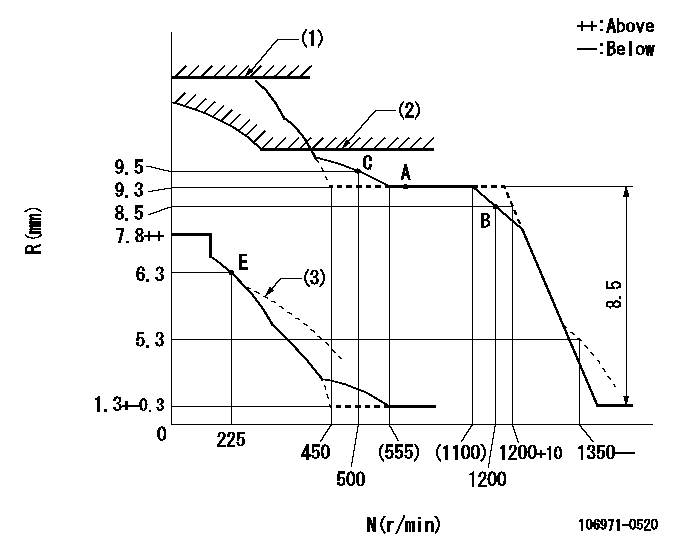
N:Pump speed
R:Rack position (mm)
(1)Rack limit using stop lever (at N = N1 or less).
(2)Excess fuel setting for starting: SXL
(3)Damper spring setting: DL
----------
N1=100r/min SXL=10.1+-0.1mm DL=5.8-0.2mm
----------
----------
N1=100r/min SXL=10.1+-0.1mm DL=5.8-0.2mm
----------
Timer adjustment
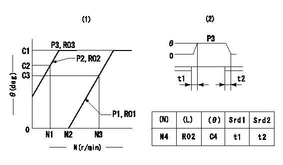
(1)Adjusting range
(2)Step response time
(N): Speed of the pump
(L): Load
(theta) Advance angle
(Srd1) Step response time 1
(Srd2) Step response time 2
1. Adjusting conditions for the variable timer
(1)Adjust the clearance between the pickup and the protrusion to L.
----------
L=1-0.2mm N4=800r/min C4=(7deg) t1=1.7--sec. t2=1.7--sec.
----------
N1=400r/min N2=1250++r/min N3=- C1=7+-0.3deg C2=3.5++deg C3=- P1=0kPa(0kgf/cm2) P2=294kPa(3kgf/cm2) P3=392kPa(4kgf/cm2) R01=0/4load R02=4/4load R03=4/4load
----------
L=1-0.2mm N4=800r/min C4=(7deg) t1=1.7--sec. t2=1.7--sec.
----------
N1=400r/min N2=1250++r/min N3=- C1=7+-0.3deg C2=3.5++deg C3=- P1=0kPa(0kgf/cm2) P2=294kPa(3kgf/cm2) P3=392kPa(4kgf/cm2) R01=0/4load R02=4/4load R03=4/4load
Speed control lever angle

F:Full speed
----------
----------
a=7deg+-5deg
----------
----------
a=7deg+-5deg
0000000901
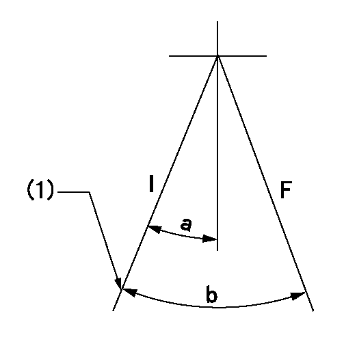
F:Full load
I:Idle
(1)Stopper bolt setting
----------
----------
a=18.5deg+-5deg b=29.5deg+-3deg
----------
----------
a=18.5deg+-5deg b=29.5deg+-3deg
Stop lever angle
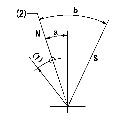
N:Pump normal
S:Stop the pump.
(1)R = aa
(2)Rack position bb
----------
aa=32mm bb=13.8+0.2mm
----------
a=10.5deg+-5deg b=36deg+-5deg
----------
aa=32mm bb=13.8+0.2mm
----------
a=10.5deg+-5deg b=36deg+-5deg
0000001501 RACK SENSOR

(VR) measurement voltage
(I) Part number of the control unit
(G) Apply red paint.
(H): End surface of the pump
1. Rack sensor adjustment (-0620)
(1)Fix the speed control lever at the full position
(2)Set the speed to N1 r/min.
(If the boost compensator is provided, apply boost pressure.)
(3)Adjust the bobbin (A) so that the rack sensor's output voltage is VR+-0.01.
(4)At that time, rack position must be Ra.
(5)Apply G at two places.
Connecting part between the joint (B) and the nut (F)
Connecting part between the joint (B) and the end surface of the pump (H)
----------
N1=700r/min Ra=9.3mm
----------
----------
N1=700r/min Ra=9.3mm
----------
Timing setting
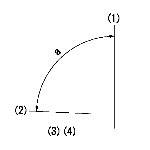
(1)Pump vertical direction
(2)Position of the coupling's key groove at the start of injection for the No. 10 cylinder.
(3)-
(4)-
----------
----------
a=(90deg)
----------
----------
a=(90deg)