Rating:
Information injection-pump assembly
ZEXEL
106961-6160
1069616160
ISUZU
1156027383
1156027383
Service parts 106961-6160 INJECTION-PUMP ASSEMBLY:
1.
_
6.
COUPLING PLATE
7.
COUPLING PLATE
8.
_
9.
_
11.
Nozzle and Holder
12.
Open Pre:MPa(Kqf/cm2)
15.7(160)/22.1(225)

15.
NOZZLE SET
Include in #1:
106961-6160
as INJECTION-PUMP ASSEMBLY
Cross reference number
ZEXEL
106961-6160
1069616160
ISUZU
1156027383
1156027383
Zexel num
Bosch num
Firm num
Name
Calibration Data:
Adjustment conditions
Test oil
1404 Test oil ISO4113 or {SAEJ967d}
1404 Test oil ISO4113 or {SAEJ967d}
Test oil temperature
degC
40
40
45
Nozzle and nozzle holder
105780-8140
Bosch type code
EF8511/9A
Nozzle
105780-0000
Bosch type code
DN12SD12T
Nozzle holder
105780-2080
Bosch type code
EF8511/9
Opening pressure
MPa
17.2
Opening pressure
kgf/cm2
175
Injection pipe
Outer diameter - inner diameter - length (mm) mm 8-3-600
Outer diameter - inner diameter - length (mm) mm 8-3-600
Overflow valve (drive side)
134424-3520
Overflow valve opening pressure (drive side)
kPa
255
221
289
Overflow valve opening pressure (drive side)
kgf/cm2
2.6
2.25
2.95
Overflow valve (governor side)
134424-2720
Overflow valve opening pressure (governor side)
kPa
255
221
289
Overflow valve opening pressure (governor side)
kgf/cm2
2.6
2.25
2.95
Tester oil delivery pressure
kPa
157
157
157
Tester oil delivery pressure
kgf/cm2
1.6
1.6
1.6
Direction of rotation (viewed from drive side)
Right R
Right R
Injection timing adjustment
Direction of rotation (viewed from drive side)
Right R
Right R
Injection order
1-8-7-6-
5-4-3-10
-9-2
Pre-stroke
mm
4
3.97
4.03
Beginning of injection position
Governor side NO.1
Governor side NO.1
Difference between angles 1
Cal 1-8 deg. 27 26.75 27.25
Cal 1-8 deg. 27 26.75 27.25
Difference between angles 2
Cal 1-7 deg. 72 71.75 72.25
Cal 1-7 deg. 72 71.75 72.25
Difference between angles 3
Cal 1-6 deg. 99 98.75 99.25
Cal 1-6 deg. 99 98.75 99.25
Difference between angles 4
Cal 1-5 deg. 144 143.75 144.25
Cal 1-5 deg. 144 143.75 144.25
Difference between angles 5
Cal 1-4 deg. 171 170.75 171.25
Cal 1-4 deg. 171 170.75 171.25
Difference between angles 6
Cal 1-3 deg. 216 215.75 216.25
Cal 1-3 deg. 216 215.75 216.25
Difference between angles 7
Cal 1-10 deg. 243 242.75 243.25
Cal 1-10 deg. 243 242.75 243.25
Difference between angles 8
Cal 1-9 deg. 288 287.75 288.25
Cal 1-9 deg. 288 287.75 288.25
Difference between angles 9
Cyl.1-2 deg. 315 314.75 315.25
Cyl.1-2 deg. 315 314.75 315.25
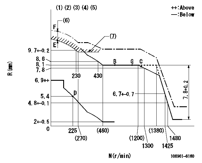
Injection quantity adjustment
Adjusting point
B
Rack position
8.1
Pump speed
r/min
700
700
700
Average injection quantity
mm3/st.
85.6
84.1
87.1
Max. variation between cylinders
%
0
-2
2
Basic
*
Fixing the lever
*
Injection quantity adjustment_02
Adjusting point
C
Rack position
7.9+-0.5
Pump speed
r/min
1250
1250
1250
Average injection quantity
mm3/st.
95.9
91.9
99.9
Max. variation between cylinders
%
0
-3
3
Fixing the lever
*
Injection quantity adjustment_03
Adjusting point
D
Rack position
5.4+-0.5
Pump speed
r/min
225
225
225
Average injection quantity
mm3/st.
8
6.6
9.4
Max. variation between cylinders
%
0
-13
13
Fixing the rack
*
Injection quantity adjustment_04
Adjusting point
F
Rack position
-
Pump speed
r/min
150
150
150
Average injection quantity
mm3/st.
137
137
Fixing the lever
*
Remarks
When manual lever is on the boost side
When manual lever is on the boost side
Test data Ex:
Governor adjustment
N:Pump speed
R:Rack position (mm)
(1)Lever ratio: RT
(2)Target shim dimension: TH
(3)Tolerance for racks not indicated: +-0.05mm.
(4)Supplied with damper spring not set.
(5)Supply solenoid operating voltage DC24V and move the solenoid body so that the excess lever reaches the excess position at the solenoid's maximum stroke.
(6)At excess fuel lever operation: not exceeding EXL
(7)Excess fuel setting for starting: SXL (N = N1)
----------
RT=0.8 TH=2.4mm EXL=2mm SXL=9.2+-0.1mm N1=320r/min
----------
----------
RT=0.8 TH=2.4mm EXL=2mm SXL=9.2+-0.1mm N1=320r/min
----------
Timer adjustment
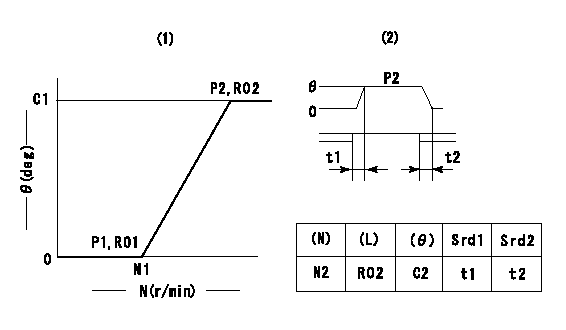
(1)Adjusting range
(2)Step response time
(N): Speed of the pump
(L): Load
(theta) Advance angle
(Srd1) Step response time 1
(Srd2) Step response time 2
1. Adjusting conditions for the variable timer
(1)Adjust the clearance between the pickup and the protrusion to L.
----------
L=1-0.2mm N2=800r/min C2=(7)deg t1=1.5--sec. t2=1.5--sec.
----------
N1=1100++r/min P1=0kPa(0kgf/cm2) P2=392kPa(4kgf/cm2) C1=7+-0.3deg R01=0/4load R02=4/4load
----------
L=1-0.2mm N2=800r/min C2=(7)deg t1=1.5--sec. t2=1.5--sec.
----------
N1=1100++r/min P1=0kPa(0kgf/cm2) P2=392kPa(4kgf/cm2) C1=7+-0.3deg R01=0/4load R02=4/4load
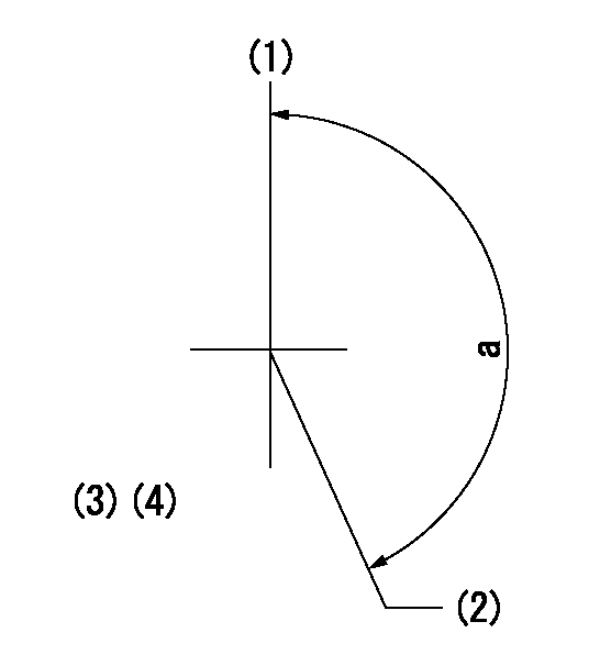
Speed control lever angle

F:Full speed
----------
----------
a=9deg+-5deg
----------
----------
a=9deg+-5deg
0000000901
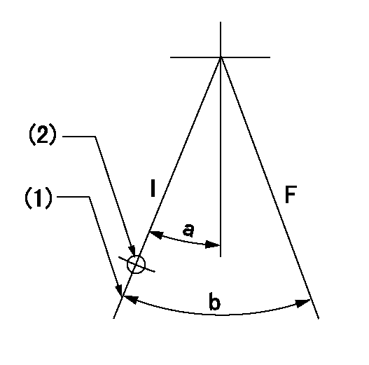
F:Full load
I:Idle
(1)Stopper bolt setting
(2)Use the hole at R = aa
----------
aa=35mm
----------
a=10deg+-5deg b=33deg+-3deg
----------
aa=35mm
----------
a=10deg+-5deg b=33deg+-3deg
Stop lever angle
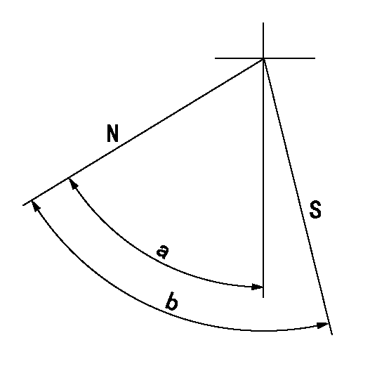
N:Pump normal
S:Stop the pump.
----------
----------
a=60deg+-5deg b=73deg+-5deg
----------
----------
a=60deg+-5deg b=73deg+-5deg
0000001101
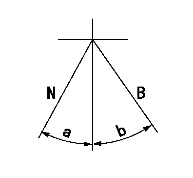
N:Normal
B:When boosted
----------
----------
a=(5deg) b=(24deg)
----------
----------
a=(5deg) b=(24deg)
0000001501 RACK SENSOR
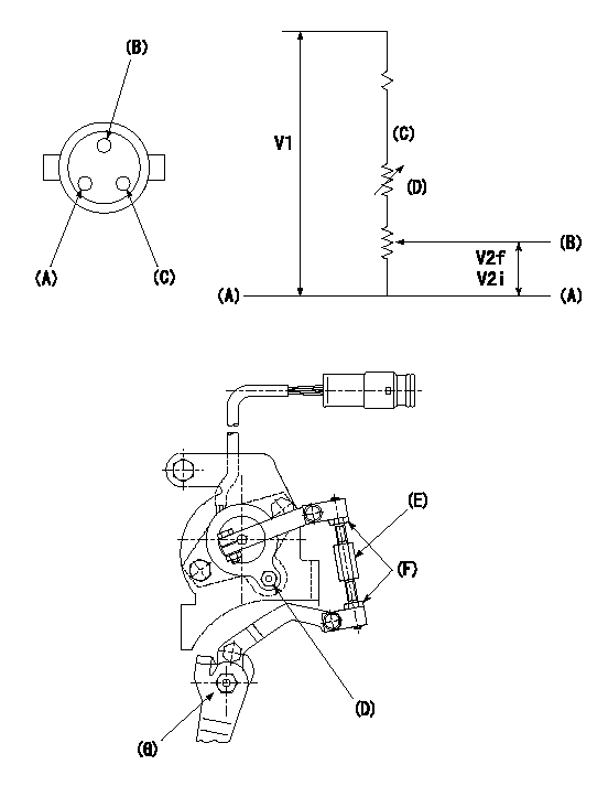
V1:Supply voltage
V2f:Full side output voltage
V2i:Idle side output voltage
(A) Black
(B) Yellow
(C) Red
(D) Trimmer
(E): Shaft
(F) Nut
(G) Load lever
1. Load sensor adjustment
(1)Connect as shown in the above diagram and apply supply voltage V1.
(2)Hold the load lever (G) against the full side.
(3)Turn the shaft so that the voltage between (A) and (B) is V2.
(4)Hold the load lever (G) against the idle side.
(5)Adjust (D) so that the voltage between (A) and (B) is V2i.
(6)Repeat the above adjustments.
(7)Tighten the nut (F) at the point satisfying the standards.
(8)Hold the load lever against the full side stopper and the idle side stopper.
(9)At this time, confirm that the full side output voltage is V2f and the idle side output voltage is V2i.
----------
V1=5+-0.02V V2f=0.15+0.03V V2i=2.35-0.03V
----------
----------
V1=5+-0.02V V2f=0.15+0.03V V2i=2.35-0.03V
----------
0000001601 SPEED SENSOR
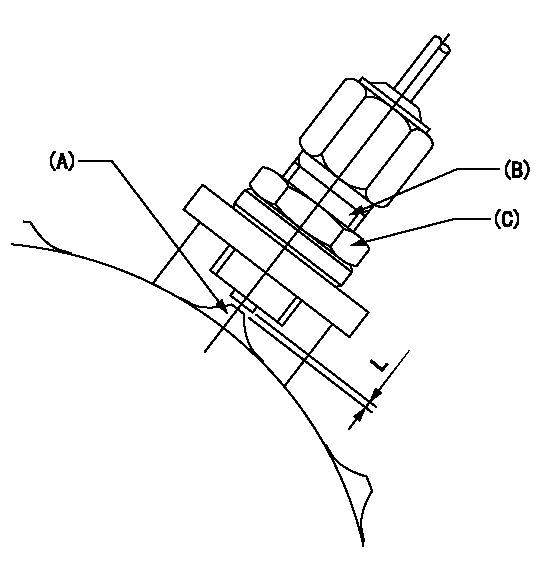
(A) Flyweight projection
(B) Pickup sensor
(c) Lock nut
Speed sensor installation
(1)Install the speed sensor so that the clearance between the sensor and the flyweight projection is L.
(This gap is the gap when the pickup sensor is returned 1 turn from where it contacts the flyweight tooth.)
----------
L=0.8~1mm
----------
----------
L=0.8~1mm
----------
Timing setting
(1)Pump vertical direction
(2)Position of "Z" mark at the No 1 cylinder's beginning of injection (governor side)
(3)B.T.D.C.: aa
(4)-
----------
aa=12deg
----------
a=(170deg)
----------
aa=12deg
----------
a=(170deg)