
Rating:
Information injection-pump assembly
ZEXEL
106961-0180
1069610180
Service parts 106961-0180 INJECTION-PUMP ASSEMBLY:
1.
_
6.
COUPLING PLATE
7.
COUPLING PLATE
8.
_
9.
_
11.
Nozzle and Holder
16600-97012
12.
Open Pre:MPa(Kqf/cm2)
19.6{200}
15.
NOZZLE SET
Include in #1:
106961-0180
as INJECTION-PUMP ASSEMBLY
Cross reference number
ZEXEL
106961-0180
1069610180
Zexel num
Bosch num
Firm num
Name
106961-0180
INJECTION-PUMP ASSEMBLY
Calibration Data:
Adjustment conditions
Test oil
1404 Test oil ISO4113 or {SAEJ967d}
1404 Test oil ISO4113 or {SAEJ967d}
Test oil temperature
degC
40
40
45
Nozzle
105015-2780
Nozzle holder
105031-4140
Opening pressure
MPa
19.6
Opening pressure
kgf/cm2
200
Injection pipe
Outer diameter - inner diameter - length (mm) mm 6-2-1050
Outer diameter - inner diameter - length (mm) mm 6-2-1050
Overflow valve
132424-0620
Overflow valve opening pressure
kPa
157
123
191
Overflow valve opening pressure
kgf/cm2
1.6
1.25
1.95
Tester oil delivery pressure
kPa
157
157
157
Tester oil delivery pressure
kgf/cm2
1.6
1.6
1.6
Direction of rotation (viewed from drive side)
Right R
Right R
Injection timing adjustment
Direction of rotation (viewed from drive side)
Right R
Right R
Injection order
10-9-4-3
-6-5-8-7
-2-1
Pre-stroke
mm
3.65
3.6
3.7
Beginning of injection position
Governor side NO.1
Governor side NO.1
Difference between angles 1
Cal 10-9 deg. 45 44.5 45.5
Cal 10-9 deg. 45 44.5 45.5
Difference between angles 2
Cal 10-4 deg. 72 71.5 72.5
Cal 10-4 deg. 72 71.5 72.5
Difference between angles 3
Cal 10-3 deg. 117 116.5 117.5
Cal 10-3 deg. 117 116.5 117.5
Difference between angles 4
Cal 10-6 deg. 144 143.5 144.5
Cal 10-6 deg. 144 143.5 144.5
Difference between angles 5
Cal 10-5 deg. 189 188.5 189.5
Cal 10-5 deg. 189 188.5 189.5
Difference between angles 6
Cal 10-8 deg. 216 215.5 216.5
Cal 10-8 deg. 216 215.5 216.5
Difference between angles 7
Cal 10-7 deg. 261 260.5 261.5
Cal 10-7 deg. 261 260.5 261.5
Difference between angles 8
Cal 10-2 deg. 288 287.5 288.5
Cal 10-2 deg. 288 287.5 288.5
Difference between angles 9
Cal 10-1 deg. 333 332.5 333.5
Cal 10-1 deg. 333 332.5 333.5
Injection quantity adjustment
Adjusting point
A
Rack position
10.9
Pump speed
r/min
700
700
700
Average injection quantity
mm3/st.
118
118
120
Max. variation between cylinders
%
0
-4
4
Basic
*
Fixing the lever
*
Injection quantity adjustment_02
Adjusting point
B
Rack position
10.9
Pump speed
r/min
1000
1000
1000
Average injection quantity
mm3/st.
113.5
110.5
116.5
Max. variation between cylinders
%
0
-4
4
Fixing the lever
*
Injection quantity adjustment_03
Adjusting point
C
Rack position
10.9
Pump speed
r/min
1200
1200
1200
Average injection quantity
mm3/st.
107
103
111
Max. variation between cylinders
%
0
-4
4
Fixing the lever
*
Injection quantity adjustment_04
Adjusting point
D
Rack position
4.5+-0.5
Pump speed
r/min
250
250
250
Average injection quantity
mm3/st.
20
18
22
Max. variation between cylinders
%
0
-10
10
Fixing the rack
*
Timer adjustment
Pump speed
r/min
300+100
Advance angle
deg.
0
0
0
Remarks
Start
Start
Timer adjustment_02
Pump speed
r/min
700
Advance angle
deg.
1.7
1.2
2.2
Timer adjustment_03
Pump speed
r/min
1000
Advance angle
deg.
3.5
3
4
Timer adjustment_04
Pump speed
r/min
1250+50
Advance angle
deg.
5.5
5
6
Remarks
Finish
Finish
Test data Ex:
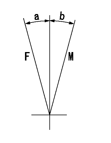
Governor adjustment
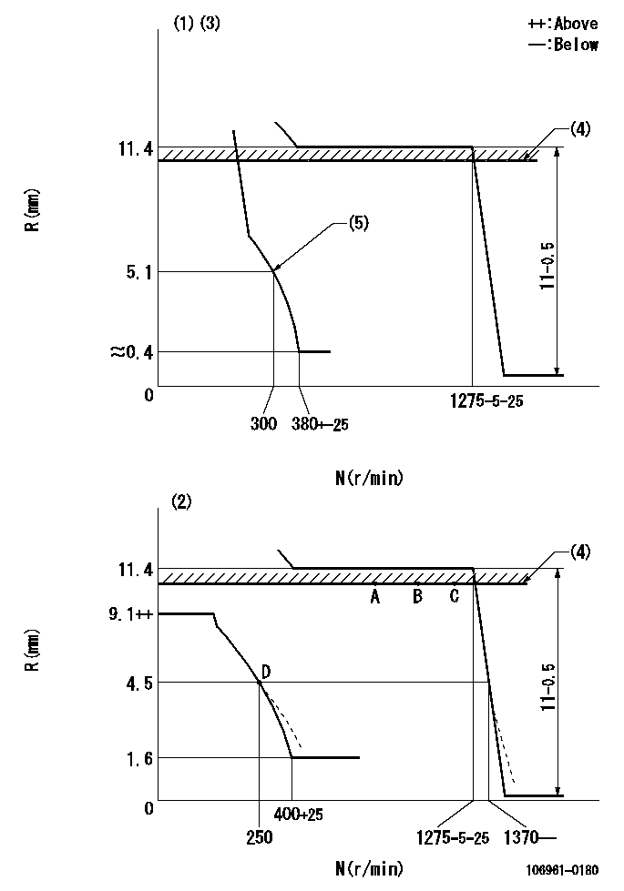
N:Pump speed
R:Rack position (mm)
(1)Adjust with speed control lever at full position (minimum-maximum speed specification)
(2)Adjust with the load control lever in the full position (variable speed specification).
(3)Beginning of damper spring operation: DL
(4)RACK LIMIT: RAL (set using stop lever)
(5)Set using the speed control lever (idle spring does not operate).
----------
DL=4.4-0.2mm RAL=10.9mm
----------
----------
DL=4.4-0.2mm RAL=10.9mm
----------
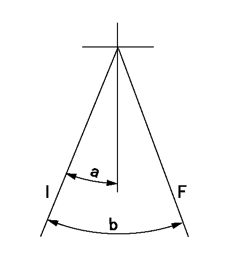
Speed control lever angle
F:Full speed
M:Minimum-maximum speed
----------
----------
a=12deg+-5deg b=10deg+-5deg
----------
----------
a=12deg+-5deg b=10deg+-5deg
0000000901
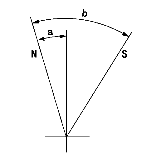
F:Full load
I:Idle
----------
----------
a=27deg+-5deg b=36deg+-3deg
----------
----------
a=27deg+-5deg b=36deg+-3deg
Stop lever angle
N:Pump normal
S:Stop the pump.
----------
----------
a=1.5deg+-5deg b=28deg+-3deg
----------
----------
a=1.5deg+-5deg b=28deg+-3deg
Have questions with 106961-0180?
Group cross 106961-0180 ZEXEL
Nissan-Diesel
Nissan-Diesel
Nissan-Diesel
Nissan-Diesel
106961-0180
INJECTION-PUMP ASSEMBLY